TikZ and PGF Manual
Libraries
71 Shape Library
71.1 Overview
In addition to the standard shapes rectangle, circle and coordinate, there exist a number of additional shapes defined in different shape libraries. Most of these shapes have been contributed by Mark Wibrow. In the present section, these shapes are described. Note that the library shapes is provided for compatibility only. Please include sublibraries like shapes.geometric or shapes.misc directly.
The appearance of shapes is influenced by numerous parameters like minimum height or inner xsep. These general parameters are documented in Section 17.2.3
In all of the examples presented in this section, the following shape example style is used:
71.2 Predefined Shapes
The three shapes rectangle, circle, and coordinate are always defined and no library needs to be loaded for them. While the coordinate shape defines only the center anchor, the other two shapes define a standard set of anchors.
-
Shape circle
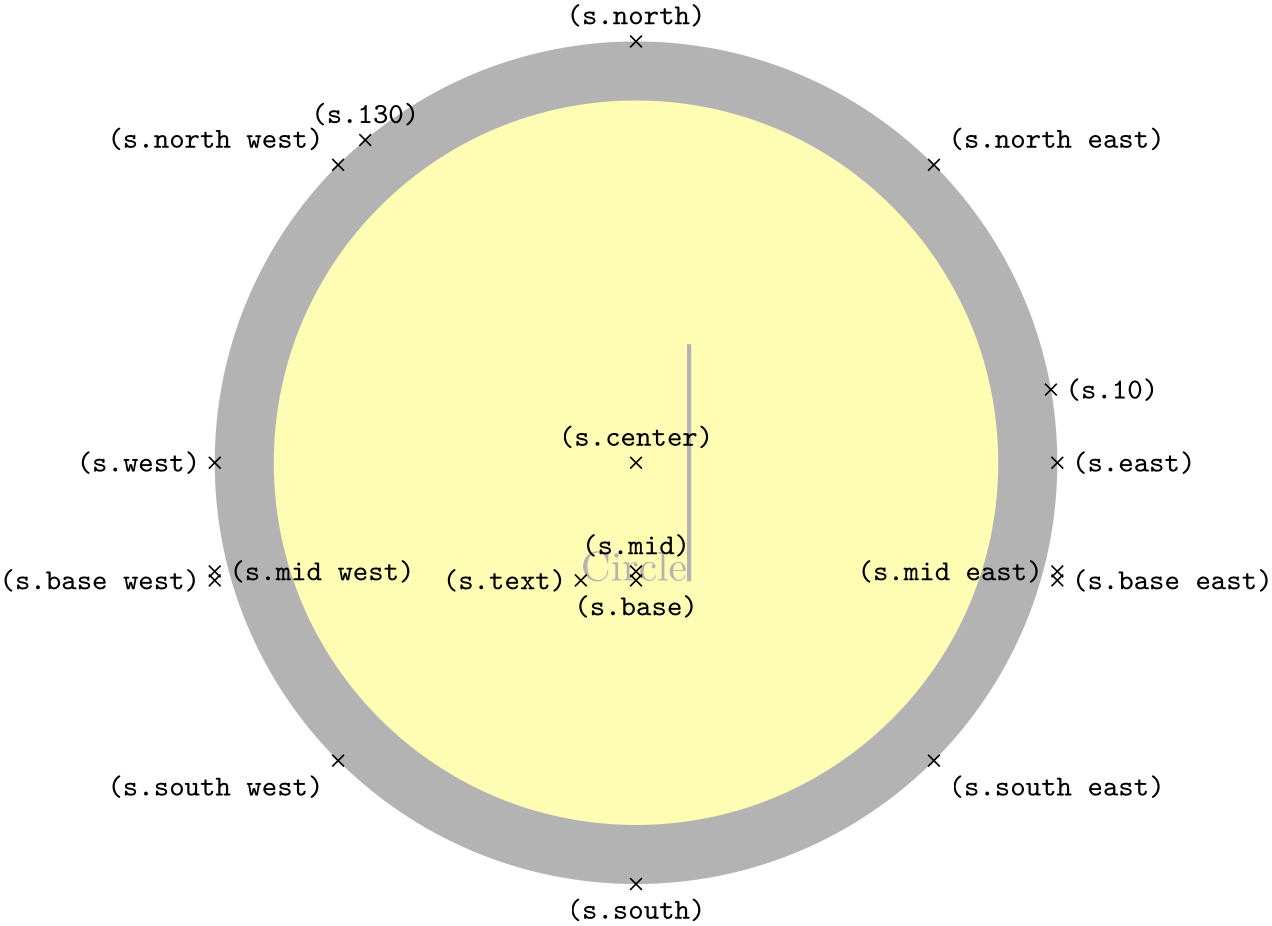
This shape draws a tightly fitting circle around the text. The following figure shows the anchors this shape defines; the anchors 10 and 130 are example of border anchors.
                    \usetikzlibrary {shapes.geometric}

                    \Huge

                    \begin{tikzpicture}

                      \node[name=s,shape=circle,shape example] {Circle\vrule width
                    1pt
                    height
                    2cm};

                      \foreach \anchor/\placement in

                        {north
                    west/above
                    left, north/above, north
                    east/above
                    right,

                         west/left, center/above, east/right,

                         mid
                    west/right, mid/above, mid
                    east/left,

                         base
                    west/left, base/below, base
                    east/right,

                         south
                    west/below
                    left, south/below, south
                    east/below
                    right,

                         text/left, 10/right, 130/above}

                         \draw[shift=(s.\anchor)] plot[mark=x] coordinates{(0,0)}

                           node[\placement] {\scriptsize\texttt{(s.\anchor)}};

                    \end{tikzpicture}
-
Shape rectangle
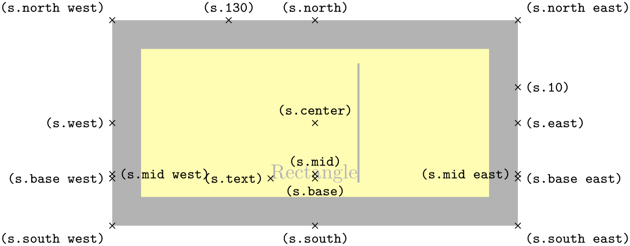
This shape, which is the standard, is a rectangle around the text. The inner and outer separations (see Section 17.2.3) influence the white space around the text. The following figure shows the anchors this shape defines; the anchors 10 and 130 are example of border anchors.
                    \usetikzlibrary {shapes.geometric}

                    \Huge

                    \begin{tikzpicture}

                      \node[name=s,shape=rectangle,shape example] {Rectangle\vrule width
                    1pt
                    height
                    2cm};

                      \foreach \anchor/\placement in

                        {north
                    west/above
                    left, north/above, north
                    east/above
                    right,

                         west/left, center/above, east/right,

                         mid
                    west/right, mid/above, mid
                    east/left,

                         base
                    west/left, base/below, base
                    east/right,

                         south
                    west/below
                    left, south/below, south
                    east/below
                    right,

                         text/left, 10/right, 130/above}

                         \draw[shift=(s.\anchor)] plot[mark=x] coordinates{(0,0)}

                           node[\placement] {\scriptsize\texttt{(s.\anchor)}};

                    \end{tikzpicture}
71.3 Geometric Shapes
-
TikZ Library shapes.geometric 
\usepgflibrary{shapes.geometric} %
LaTeX
and plain
TeX
and pure pgf
\usepgflibrary[shapes.geometric] % ConTeXt and pure pgf
\usetikzlibrary{shapes.geometric} %
LaTeX
and plain
TeX
when using TikZ
\usetikzlibrary[shapes.geometric] % ConTeXt when using TikZ
This library defines different shapes that correspond to basic geometric objects like ellipses or polygons.
-
Shape diamond 
-
/pgf/aspect=⟨value⟩ (no default, initially 1.0) 
This shape is a diamond tightly fitting the text box. The ratio between width and height is 1 by default, but can be changed by setting the shape aspect ratio using the following pgf key (to use this key in TikZ simply remove the /pgf/ path).
The aspect is a recommendation for the quotient of the width and the height of a shape. This key calls the macro \pgfsetshapeaspect.
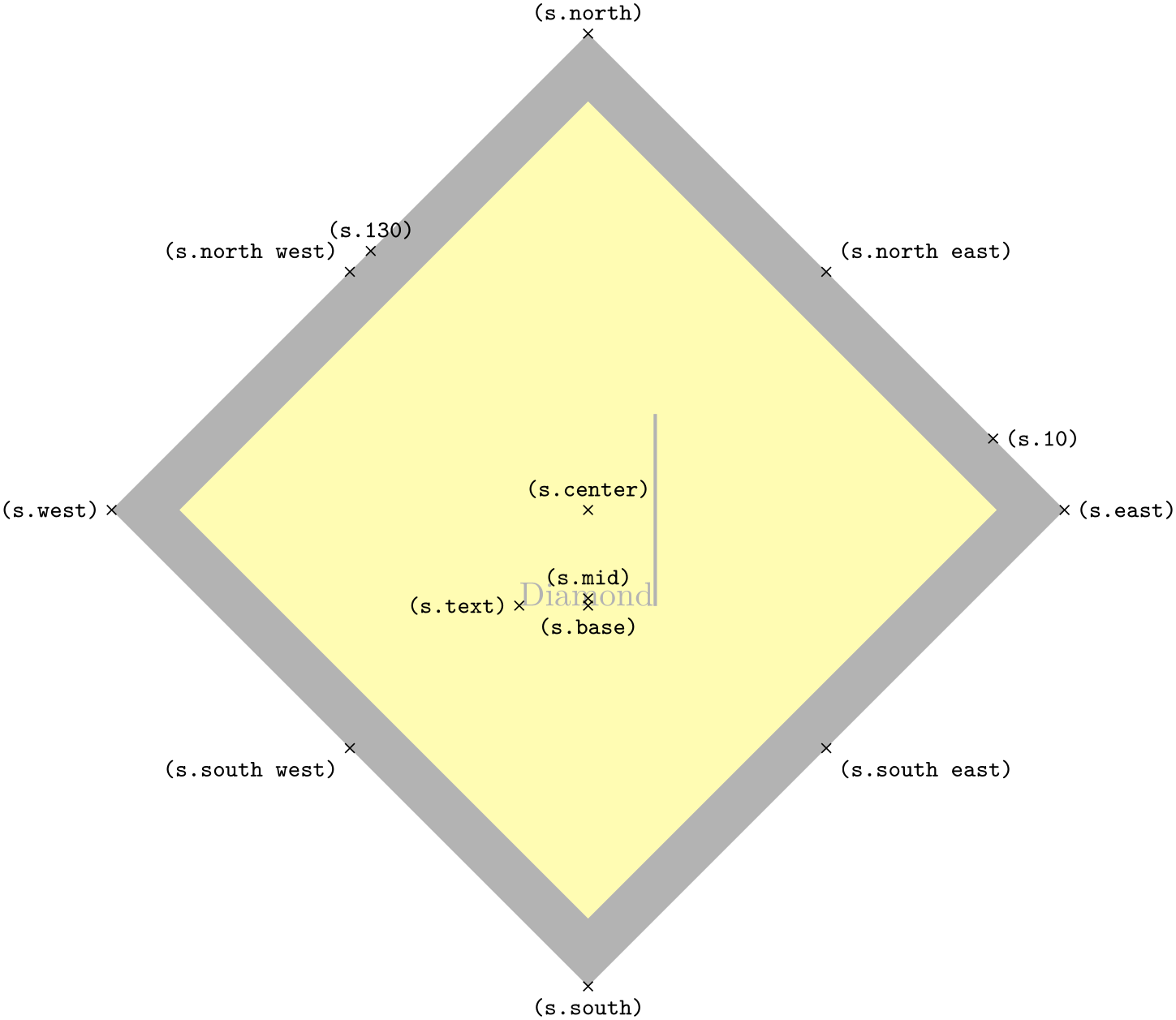
The following figure shows the anchors this shape defines; the anchors 10 and 130 are example of border anchors.
                    \usetikzlibrary {shapes.geometric}

                    \Huge

                    \begin{tikzpicture}

                      \node[name=s,shape=diamond,shape example] {Diamond\vrule width
                    1pt
                    height
                    2cm};

                      \foreach \anchor/\placement in

                        {north
                    west/above
                    left, north/above, north
                    east/above
                    right,

                         west/left, center/above, east/right,

                         mid/above,

                         base/below,

                         south
                    west/below
                    left, south/below, south
                    east/below
                    right,

                         text/left, 10/right, 130/above}

                         \draw[shift=(s.\anchor)] plot[mark=x] coordinates{(0,0)}

                           node[\placement] {\scriptsize\texttt{(s.\anchor)}};

                    \end{tikzpicture}
-
Shape ellipse
This shape is an ellipse tightly fitting the text box, if no inner separation is given. The following figure shows the anchors this shape defines; the anchors 10 and 130 are example of border anchors.

                    \usetikzlibrary {shapes.geometric}

                    \Huge

                    \begin{tikzpicture}

                      \node[name=s,shape=ellipse,shape example] {Ellipse\vrule width
                    1pt
                    height
                    2cm};

                      \foreach \anchor/\placement in

                        {north
                    west/above
                    left, north/above, north
                    east/above
                    right,

                         west/left, center/above, east/right,

                         mid
                    west/right, mid/above, mid
                    east/left,

                         base
                    west/left, base/below, base
                    east/right,

                         south
                    west/below
                    left, south/below, south
                    east/below
                    right,

                         text/left, 10/right, 130/above}

                         \draw[shift=(s.\anchor)] plot[mark=x] coordinates{(0,0)}

                           node[\placement] {\scriptsize\texttt{(s.\anchor)}};

                    \end{tikzpicture}
-
Shape trapezium 
-
/pgf/trapezium left angle=⟨angle⟩ (no default, initially 60) 
-
/pgf/trapezium right angle=⟨angle⟩ (no default, initially 60) 
-
/pgf/trapezium angle=⟨angle⟩(style, no default) 
-
/pgf/trapezium stretches=⟨boolean⟩ (default true) 
-
/pgf/trapezium stretches body=⟨boolean⟩ (default true) 
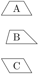
This shape is a trapezium, that is, a quadrilateral with a single pair of parallel lines (this can sometimes be known as a trapezoid). The trapezium shape supports the rotation of the shape border, as described in Section 17.2.3.
The lower internal angles at the lower corners of the trapezium can be specified independently, and the resulting extensions are in addition to the natural dimensions of the node contents (which includes any inner sep.
                    \usetikzlibrary {shapes.geometric}

                    \begin{tikzpicture}[every node/.style={trapezium, draw}]

                       \node at
                    (0,2) {A};

                       \node[trapezium left angle=75, trapezium right angle=45]

                             at
                    (0,1) {B};

                       \node[trapezium left angle=120, trapezium right angle=60]

                             at
                    (0,0) {C};

                    \end{tikzpicture}
The pgf keys to set the lower internal angles of the trapezium are shown below. To use these keys in TikZ, simply remove the /pgf/ path.
Sets the lower internal angle of the left side.
Sets the lower internal angle of the right side.
This key stores no value itself, but sets the value of the previous two keys to ⟨angle⟩.
Regardless of the rotation of the shape border, the width and height of the trapezium are as follows:
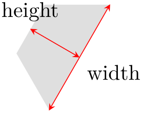
                    \usetikzlibrary {shapes.geometric}

                    \begin{tikzpicture}[>=stealth, every node/.style={text=black},

                        shape border uses incircle, shape border rotate=60]

                      \node [trapezium, fill=gray!25, minimum width=2cm] (t) {};

                      \draw [red, <->] (t.bottom left corner) --
                    (t.bottom right corner)

                        node
                    [midway, below right] {width};

                      \draw [red, <->] (t.top side) --
                    (t.bottom side)

                        node
                    [at start, above] {height};

                    \end{tikzpicture}
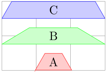
This key controls whether pgf allows the width and the height of the trapezium to be enlarged independently, when considering any minimum size specification. This is initially false, ensuring that the shape “looks the same but bigger” when enlarged.

                        \usetikzlibrary {shapes.geometric}

                        \tikzset{my node/.style={trapezium, fill=#1!20, draw=#1!75, text=black}}

                        \begin{tikzpicture}

                          \draw [help lines] grid
                        (3,2);

                          \node [my node=red]                                      {A};

                          \node [my node=green, minimum height=1.5cm] at
                        (1, 1.25) {B};

                          \node [my node=blue,  minimum width=1.5cm]  at
                        (2, 0)    {C};

                        \end{tikzpicture}
By setting ⟨boolean⟩ to true, the trapezium can be stretched horizontally or vertically.

                        \usetikzlibrary {shapes.geometric}

                        \tikzset{my node/.style={trapezium, fill=#1!20, draw=#1!75, text=black}}

                        \begin{tikzpicture}

                        \tikzset{trapezium stretches=true}

                          \draw [help lines] grid
                        (3,2);

                          \node [my node=red]                                      {A};

                          \node [my node=green, minimum height=1.5cm] at
                        (1, 1.25) {B};

                          \node [my node=blue,  minimum width=1.5cm]  at
                        (2, 0)    {C};

                        \end{tikzpicture}
This is similar to the trapezium stretches key except that when ⟨boolean⟩ is true, pgf enlarges only the body of the trapezium when applying minimum width.
                        \usetikzlibrary {shapes.geometric}

                        \tikzset{my node/.style={trapezium, fill=#1!20, draw=#1!75, text=black}}

                        \begin{tikzpicture}

                          \draw [help lines] grid
                        (3,2);

                          \node [my node=red]                      at
                        (1.5,.25)  {A};

                          \node [my node=green, minimum width=3cm, trapezium stretches]

                            at
                        (1.5,1)    {B};

                          \node [my node=blue,  minimum width=3cm, trapezium stretches body]

                            at
                        (1.5,1.75) {C};

                        \end{tikzpicture}
The anchors for the trapezium are shown below. The anchor 160 is an example of a border anchor.
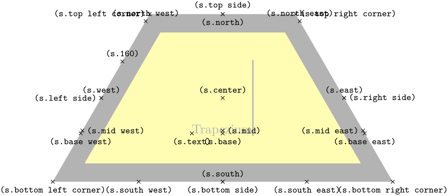
                    \usetikzlibrary {shapes.geometric}

                    \Huge

                    \begin{tikzpicture}

                      \node[name=s, shape=trapezium, shape example, inner sep=1cm]

                        {Trapezium\vrule width
                    1pt
                    height
                    2cm};

                      \foreach \anchor/\placement in

                        {bottom
                    left
                    corner/below, top
                    right
                    corner/right,

                         top
                    left
                    corner/left,     bottom
                    right
                    corner/below,

                         bottom
                    side/below,        left
                    side/left,

                         right
                    side/right,         top
                    side/above,

                         center/above,   text/below,      mid/right,       base/below,

                         mid
                    west/right, base
                    west/below, mid
                    east/left,   base
                    east/below,

                         west/above,     east/above,      north/below,     south/above,

                         north
                    west/above, north
                    east/above,

                         south
                    west/below, south
                    east/below, 160/above}

                      \draw[shift=(s.\anchor)] plot[mark=x] coordinates{(0,0)}

                        node[\placement] {\scriptsize\texttt{(s.\anchor)}};

                    \end{tikzpicture}
-
Shape semicircle 
This shape is a semicircle, which tightly fits the node contents. This shape supports the rotation of the shape border, as described in Section 17.2.3. The anchors for the semicircle shape are shown below. Anchor 30 is an example of a border anchor.
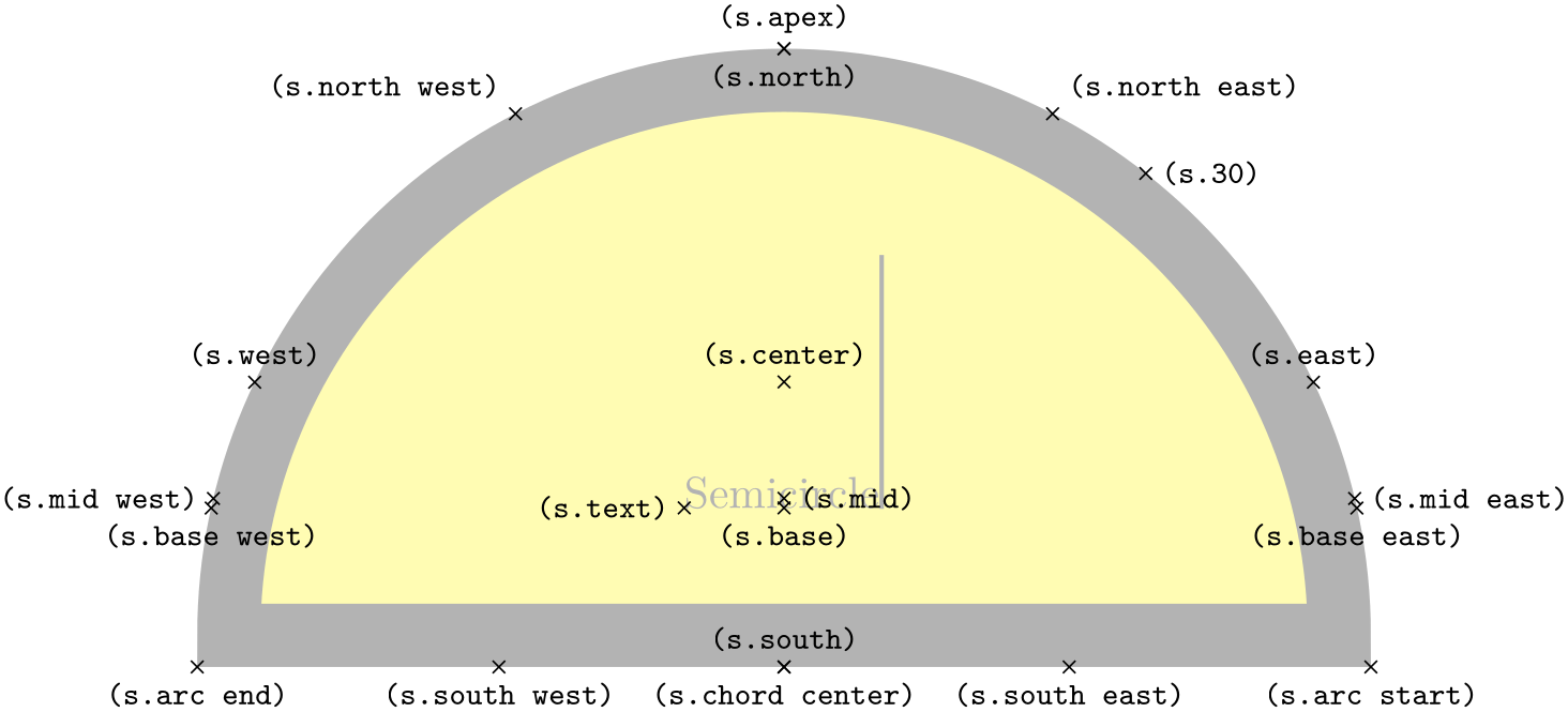
                    \usetikzlibrary {shapes.geometric}

                    \Huge

                    \begin{tikzpicture}

                      \node[name=s,shape=semicircle,shape border rotate=0,shape example, inner sep=1cm]

                        {Semicircle\vrule width
                    1pt
                    height
                    2cm};

                      \foreach \anchor/\placement in

                        {apex/above,      arc
                    start/below, arc
                    end/below,  chord
                    center/below,

                         center/above,    base/below,      mid/right,      text/left,

                         base
                    west/below, base
                    east/below, mid
                    west/left, mid
                    east/right,

                         north/below,     south/above,     east/above,     west/above,

                         north
                    west/above
                    left, north
                    east/above
                    right,

                         south
                    west/below,      south
                    east/below, 30/right}

                         \draw[shift=(s.\anchor)] plot[mark=x] coordinates{(0,0)}

                           node[\placement] {\scriptsize\texttt{(s.\anchor)}};

                    \end{tikzpicture}
-
Shape regular polygon 
-
/pgf/regular polygon sides=⟨integer⟩ (no default, initially 5) 
This shape is a regular polygon, which, by default, is drawn so that a side (rather than a corner) is always at the bottom. This shape supports the rotation as described in Section 17.2.3, but the border of the polygon is always constructed using the incircle, whose radius is calculated to tightly fit the node contents (including any inner sep).

                    \usetikzlibrary {shapes.geometric}

                    \begin{tikzpicture}

                      \foreach \a in
                    {3,...,7}{

                        \draw[red, dashed] (\a*2,0)  circle(0.5cm);

                        \node[regular polygon, regular polygon sides=\a, draw,

                         inner sep=0.3535cm] at
                    (\a*2,0) {};

                       }

                    \end{tikzpicture}
If the node is enlarged to any specified minimum size, this is interpreted as the diameter of the circumcircle, that is, the circle that passes through all the corners of the polygon border.

                    \usetikzlibrary {shapes.geometric}

                    \begin{tikzpicture}

                      \foreach \a in
                    {3,...,7}{

                        \draw[blue, dashed] (\a*2,0)  circle(0.5cm);

                        \node[regular polygon, regular polygon sides=\a, minimum size=1cm, draw] at
                    (\a*2,0) {};

                       }

                    \end{tikzpicture}
There is a pgf key to set the number of sides for the regular polygon. To use this key in TikZ, simply remove the /pgf/ path.
The anchors for a regular polygon shape are shown below. The anchor 75 is an example of a border anchor.

                    \usetikzlibrary {shapes.geometric}

                    \Huge

                    \begin{tikzpicture}

                      \node[name=s, shape=regular polygon, shape example, inner sep=.5cm]

                        {Regular
                    Polygon\vrule width
                    1pt
                    height
                    2cm};

                      \foreach \anchor/\placement in

                        {corner
                    1/above, corner
                    2/above, corner
                    3/left, corner
                    4/right, corner
                    5/above,

                         side
                    1/above,   side
                    2/left,    side
                    3/below,  side
                    4/right,   side
                    5/above,

                         center/above, text/left,  mid/right,   base/below, 75/above,

                         west/above,   east/above, north/below, south/above,

                         north
                    east/below, south
                    east/above, north
                    west/below, south
                    west/above}

                      \draw[shift=(s.\anchor)] plot[mark=x] coordinates{(0,0)}

                        node[\placement] {\scriptsize\texttt{(s.\anchor)}};

                    \end{tikzpicture}
-
Shape star 
-
/pgf/star points=⟨integer⟩ (no default, initially 5) 
-
/pgf/star point height=⟨distance⟩ (no default, initially .5cm) 
-
/pgf/star point ratio=⟨number⟩ (no default, initially 1.5) 
This shape is a star, which by default (minus any transformations) is drawn with the first point pointing upwards. This shape supports the rotation as described in Section 17.2.3, but the border of the star is always constructed using the incircle.
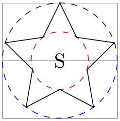
A star should be thought of as having a set of “inner points” and “outer points”. The inner points of the border are based on the radius of the circle which tightly fits the node contents, and the outer points are based on the circumcircle, the circle that passes through every outer point. Any specified minimum size, width or height, is interpreted as the diameter of the circumcircle.
                    \usetikzlibrary {shapes.geometric}

                    \begin{tikzpicture}

                       \draw [help lines]   (0,0) grid
                    (2,2);

                       \draw [blue, dashed]  (1,1) circle(1cm);

                       \draw [red, dashed] (1,1) circle(.5cm);

                       \node [star, star point height=.5cm, minimum size=2cm, draw]

                           at
                    (1,1) {S};

                    \end{tikzpicture}
The pgf keys to set the number of star points, and the height of the star points, are shown below. To use these keys in TikZ, simply remove the /pgf/ path.
Sets the number of points for the star.
Sets the height of the star points. This is the distance between the inner point and outer point radii. If the star is enlarged to some specified minimum size, the inner radius is increased to maintain the point height.
Sets the ratio between the inner point and outer point radii. If the star is enlarged to some specified minimum size, the inner radius is increased to maintain the ratio.
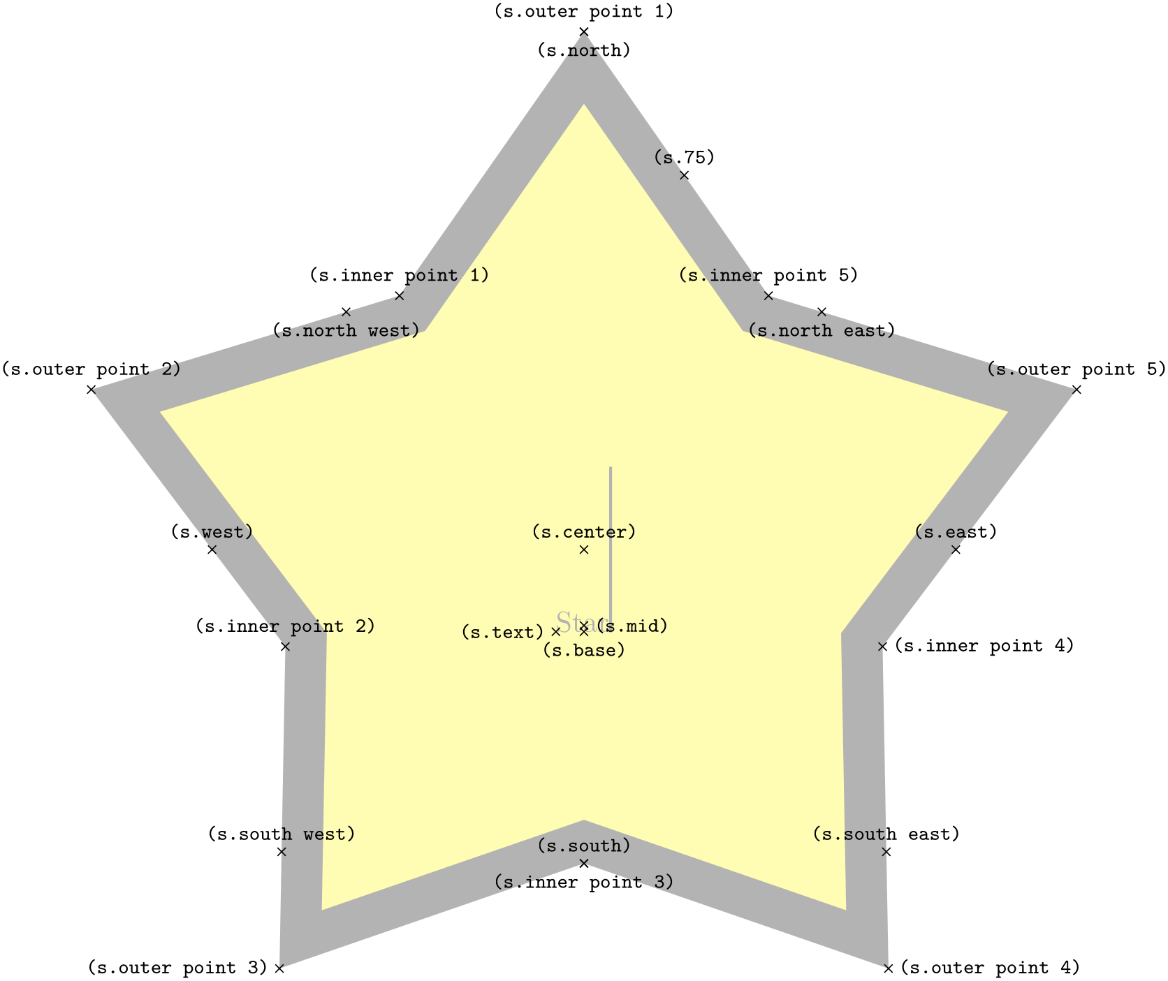
The inner and outer points form the principal anchors for the star, as shown below (anchor 75 is an example of a border anchor).
                    \usetikzlibrary {shapes.geometric}

                    \Huge

                    \begin{tikzpicture}

                      \node[name=s, shape=star, star points=5, star point ratio=1.65, shape example, inner sep=1.5cm]

                        {Star\vrule width
                    1pt
                    height
                    2cm};

                      \foreach \anchor/\placement in

                         {inner
                    point
                    1/above, inner
                    point
                    2/above, inner
                    point
                    3/below, inner
                    point
                    4/right,

                          inner
                    point
                    5/above, outer
                    point
                    1/above, outer
                    point
                    2/above, outer
                    point
                    3/left,

                          outer
                    point
                    4/right, outer
                    point
                    5/above,

                          center/above, text/left,  mid/right,   base/below, 75/above,

                             west/above,   east/above, north/below, south/above,

                             north
                    east/below, south
                    east/above, north
                    west/below, south
                    west/above}

                      \draw[shift=(s.\anchor)] plot[mark=x] coordinates{(0,0)}

                        node[\placement] {\scriptsize\texttt{(s.\anchor)}};

                    \end{tikzpicture}
-
Shape isosceles triangle 
-
/pgf/isosceles triangle apex angle=⟨angle⟩ (no default, initially 30) 
-
/pgf/isosceles triangle stretches=⟨boolean⟩ (default false) 
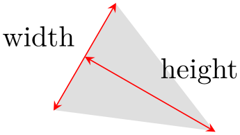
This shape is an isosceles triangle, which supports the rotation of the shape border, as described in Section 17.2.3. The angle of rotation determines the direction in which the apex of the triangle points (provided no other transformations are applied). However, regardless of the rotation of the shape border, the width and height are always considered as follows:
                    \usetikzlibrary {shapes.geometric}

                    \begin{tikzpicture}[>=stealth, every node/.style={text=black},

                        shape border uses incircle, shape border rotate=-30]

                      \node [isosceles triangle, fill=gray!25, minimum width=1.5cm] (t) {};

                      \draw [red, <->] (t.left corner) --
                    (t.right corner)

                        node
                    [midway, above left] {width};

                      \draw [red, <->] (t.apex) --
                    (t.lower side)

                        node
                    [midway, above right] {height};

                    \end{tikzpicture}
There are pgf keys to customize this shape. To use these keys in TikZ, simply remove the /pgf/ path.
Sets the angle of the apex of the isosceles triangle.
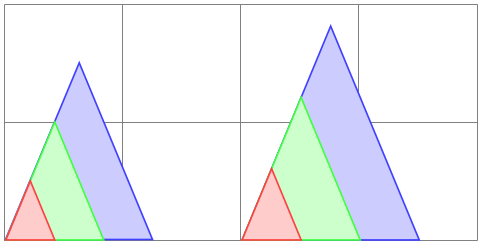
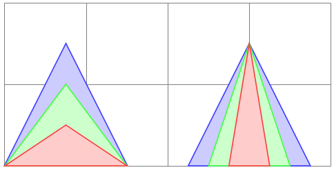
By default ⟨boolean⟩ is false. This means, that when applying any minimum width or minimum height requirements, increasing the height will increase the width (and vice versa), in order to keep the apex angle the same.
                        \usetikzlibrary {shapes.geometric}

                        \begin{tikzpicture}[paint/.style={draw=#1!75, fill=#1!20}]

                          \tikzset{every node/.style={isosceles triangle, draw, inner sep=0pt,

                            anchor=left corner, shape border rotate=90}}

                          \draw[help lines] grid(4,2);

                          \foreach \a/\c in
                        {1.5/blue, 1/green, 0.5/red}{

                            \node[paint=\c, minimum height=\a cm] at
                        (0,0) {};

                            \node[paint=\c, minimum width=\a cm] at
                        (2,0) {};

                          }

                        \end{tikzpicture}
However, by setting ⟨boolean⟩ to true, minimum width and height can be applied independently.
                        \usetikzlibrary {shapes.geometric}

                        \begin{tikzpicture}[paint/.style={draw=#1!75, fill=#1!20}]

                          \tikzset{every node/.style={isosceles triangle, draw, inner sep=0pt,

                             anchor=south, shape border rotate=90, isosceles triangle stretches}}

                          \draw[help lines] grid(4,2);

                          \foreach \a/\c in
                        {1.5/blue, 1/green, 0.5/red}{

                            \node[paint=\c, minimum height=\a cm, minimum width=1.5cm] at
                        (0.75,0) {};

                            \node[paint=\c, minimum width=\a cm, minimum height=1.5cm] at
                        (3,0)    {};

                          }

                        \end{tikzpicture}
The anchors for the isosceles triangle are shown below (anchor 150 is an example of a border anchor). Note that, somewhat confusingly, the anchor names such as left side and right corner are named as if the triangle is rotated to 90 degrees. Note also that the center anchor does not necessarily correspond to any kind of geometric center.

                    \usetikzlibrary {shapes.geometric}

                    \Huge

                    \begin{tikzpicture}

                      \node[name=s, shape=isosceles triangle, shape example, inner xsep=1cm]

                        {Isosceles
                    Triangle\vrule width
                    1pt
                    height
                    2cm};

                      \foreach \anchor/\placement in

                        {apex/above,      left
                    corner/right, right
                    corner/right,

                         left
                    side/above, right
                    side/below,  lower
                    side/right,

                         center/above,    text/right,        150/above,

                         mid/right,       mid
                    west/above,    mid
                    east/right,

                         base/below,      base
                    west/below,   base
                    east/below,

                         west/above, east/below, north/below, south/above,

                         north
                    west/below, north
                    east/below,

                         south
                    west/above, south
                    east/above}

                      \draw[shift=(s.\anchor)] plot[mark=x] coordinates{(0,0)}

                        node[\placement] {\scriptsize\texttt{(s.\anchor)}};

                    \end{tikzpicture}
-
Shape kite 
-
/pgf/kite upper vertex angle=⟨angle⟩ (no default, initially 120) 
-
/pgf/kite lower vertex angle=⟨angle⟩ (no default, initially 60) 
-
/pgf/kite vertex angles=⟨angle specification⟩(no default) 
This shape is a kite, which supports the rotation of the shape border, as described in Section 17.2.3. There are pgf keys to specify the upper and lower vertex angles of the kite. To use these keys in TikZ, simply remove the /pgf/ path.
Sets the upper internal angle of the kite.
Sets the lower internal angle of the kite.
This key sets the keys for both the upper and lower vertex angles (it stores no value itself). ⟨angle specification⟩ can be pair of angles in the form ⟨upper angle⟩ and ⟨lower angle⟩, or a single angle. In this latter case, both the upper and lower vertex angles will be the same.

                    \usetikzlibrary {shapes.geometric}

                    \begin{tikzpicture}[every node/.style={kite, draw}]

                      \node[kite upper vertex angle=135, kite lower vertex angle=70] at
                    (0,0) {A};

                      \node[kite vertex angles=90 and 45] at
                    (1,0) {B};

                      \node[kite vertex angles=60]        at
                    (2,0) {C};

                    \end{tikzpicture}
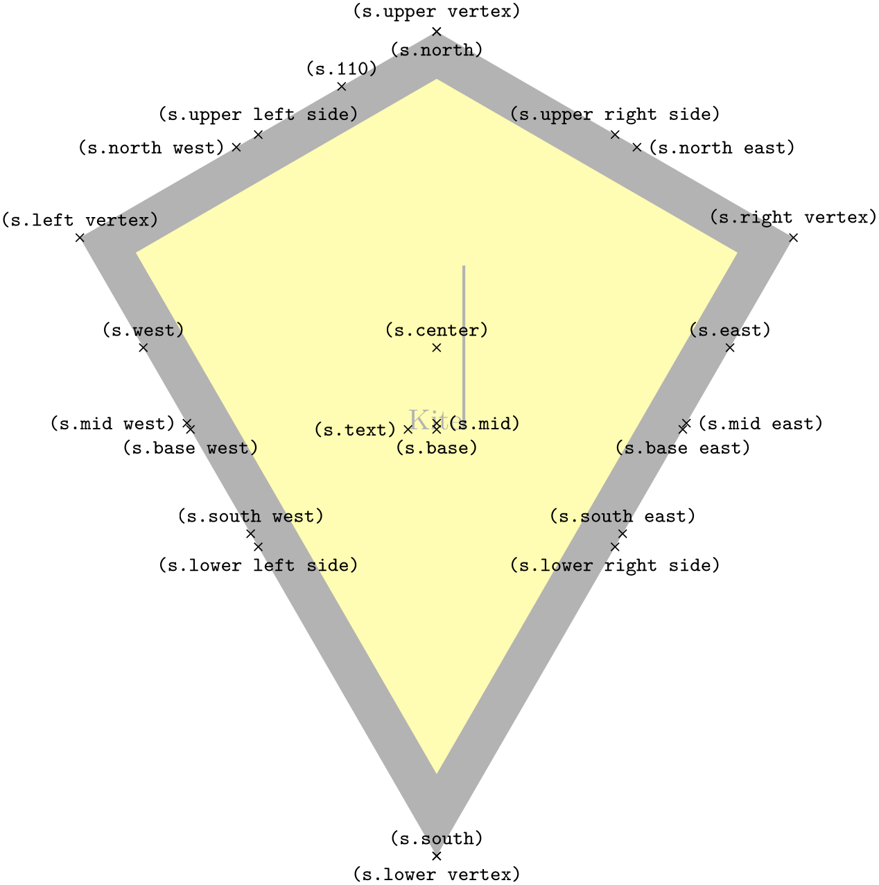
The anchors for the kite are shown below. Anchor 110 is an example of a border anchor.
                    \usetikzlibrary {shapes.geometric}

                    \Huge

                    \begin{tikzpicture}

                      \node[name=s, shape=kite, shape example, inner sep=1.5cm]

                        {Kite\vrule width
                    1pt
                    height
                    2cm};

                      \foreach \anchor/\placement in

                        {upper
                    vertex/above, left
                    vertex/above,    lower
                    vertex/below,

                         right
                    vertex/above, upper
                    left
                    side/above, upper
                    right
                    side/above,

                         lower
                    left
                    side/below, lower
                    right
                    side/below,

                         center/above,   text/left,       mid/right,        base/below,

                         mid
                    west/left,  base
                    west/below, mid
                    east/right,   base
                    east/below,

                         west/above,     east/above,      north/below,     south/above,

                         north
                    west/left, north
                    east/right,

                         south
                    west/above, south
                    east/above, 110/above}

                      \draw[shift=(s.\anchor)] plot[mark=x] coordinates{(0,0)}

                        node[\placement] {\scriptsize\texttt{(s.\anchor)}};

                    \end{tikzpicture}
-
Shape dart 
-
/pgf/dart tip angle=⟨angle⟩ (no default, initially 45) 
-
/pgf/dart tail angle=⟨angle⟩ (no default, initially 135) 
This shape is a dart (which can also be known as an arrowhead or concave kite). This shape supports the rotation of the shape border, as described in Section 17.2.3. The angle of the border rotation determines the direction in which the dart points (unless other transformations have been applied).
There are pgf keys to set the angle for the ‘tip’ of the dart and the angle between the ‘tails’ of the dart. To use these keys in TikZ, simply remove the /pgf/ path.

                    \usetikzlibrary {shapes.geometric}

                    \begin{tikzpicture}

                       \node[dart, draw, gray, shape border uses incircle, shape border rotate=45]

                           (d) {dart};

                       \draw [<->] (d.tip)++(202.5:.5cm) arc(202.5:247.5:.5cm);

                       \node [left=.5cm] at
                    (d.tip) {tip
                    angle};

                       \draw [<->] (d.tail center)++(157.5:.5cm) arc(157.5:292.5:.5cm);

                       \node [right] at
                    (d.tail center) {tail
                    angle};

                    \end{tikzpicture}
Sets the angle at the tip of the dart.
Sets the angle between the tails of the dart.
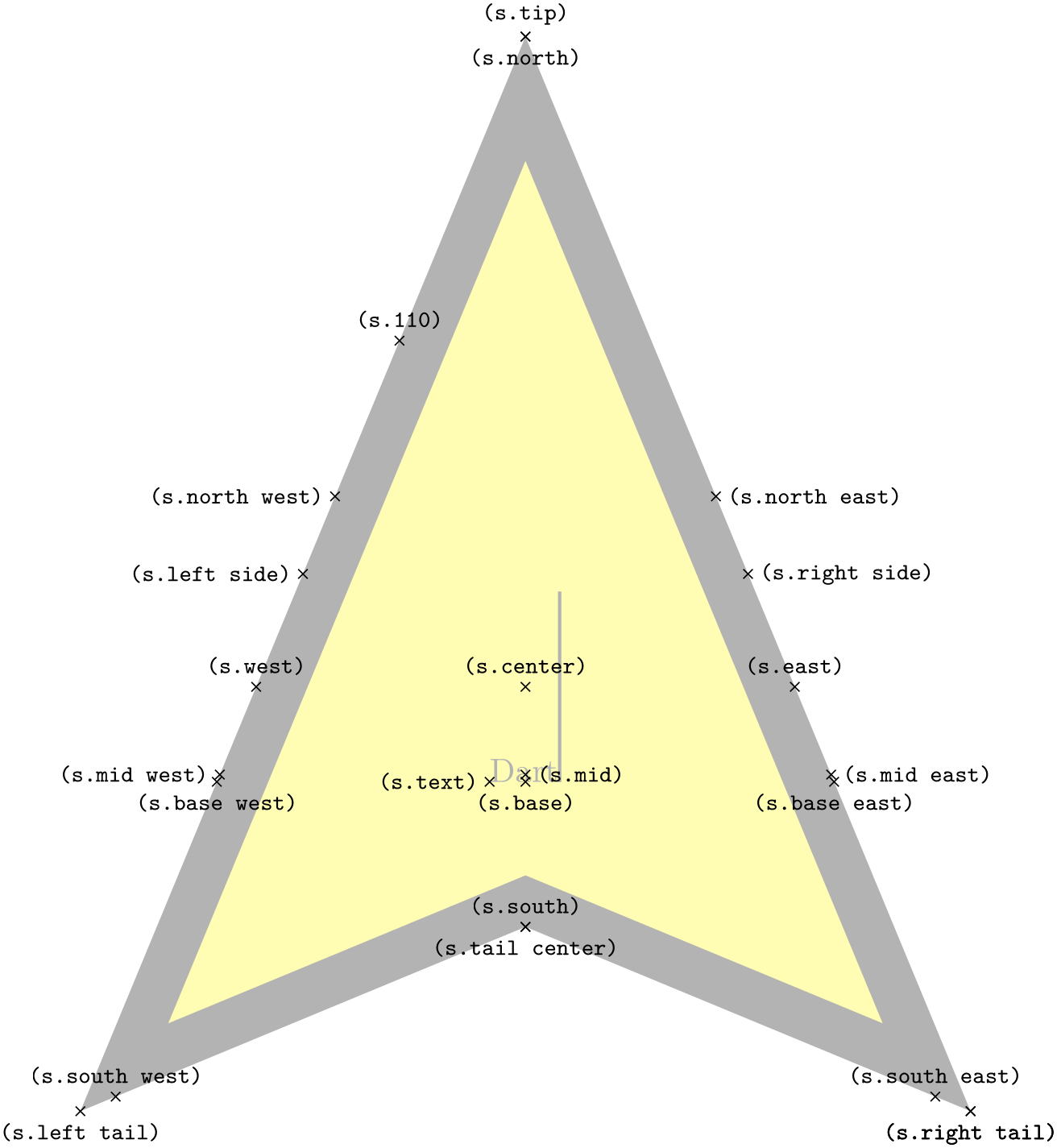
The anchors for the dart shape are shown below (note that the shape is rotated 90 degrees anti-clockwise). Anchor 110 is an example of a border anchor.
                    \usetikzlibrary {shapes.geometric}

                    \Huge

                    \begin{tikzpicture}

                      \node[name=s, shape=dart, shape border rotate=90, shape example, inner sep=1.25cm]

                        {Dart\vrule width
                    1pt
                    height
                    2cm};

                      \foreach \anchor/\placement in

                        {tip/above,       tail
                    center/below, right
                    tail/below,

                         left
                    tail/below, right
                    tail/below,  left
                    side/left,   right
                    side/right,

                         center/above,    text/left,         mid/right,        base/below,

                         mid
                    west/left,   base
                    west/below,   mid
                    east/right,   base
                    east/below,

                         west/above,      east/above,        north/below,      south/above,

                         north
                    west/left, north
                    east/right,  south
                    west/above, south
                    east/above,

                         110/above}

                      \draw[shift=(s.\anchor)] plot[mark=x] coordinates{(0,0)}

                        node[\placement] {\scriptsize\texttt{(s.\anchor)}};

                    \end{tikzpicture}
-
Shape circular sector 
-
/pgf/circular sector angle=⟨angle⟩ (no default, initially 60) 
This shape is a circular sector (which can also be known as a wedge). This shape supports the rotation of the shape border, as described in Section 17.2.3. The angle of the border rotation determines the direction in which the ‘apex’ of the sector points (unless other transformations have been applied).

                    \usetikzlibrary {shapes.geometric}

                    \begin{tikzpicture}[

                       every node/.style={circular sector, shape border uses incircle, draw},

                    ]

                       \node at
                    (0,0) {A};

                       \node [shape border rotate=30] at
                    (1.5,0) {A};

                    \end{tikzpicture}
There is a pgf key to set the central angle of the sector, which is expected to be less than 180 degrees. To use this key in TikZ, simply remove the /pgf/ path.
Sets the central angle of the sector.
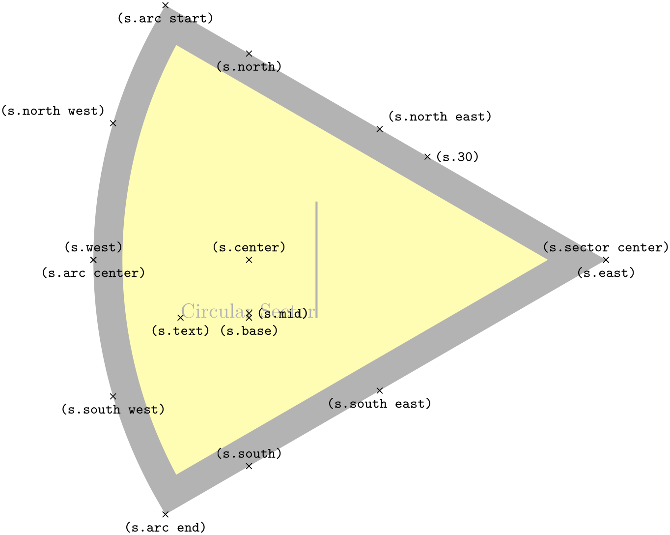
The anchors for the circular sector shape are shown below. Anchor 30 is an example of a border anchor.
                    \usetikzlibrary {shapes.geometric}

                    \Huge

                    \begin{tikzpicture}

                      \node[name=s,shape=circular sector,  style=shape example, inner sep=1cm]

                          {Circular
                    Sector\vrule width
                    1pt
                    height
                    2cm};

                      \foreach \anchor/\placement in

                       {sector
                    center/above, arc
                    start/below, arc
                    end/below, arc
                    center/below,

                        center/above,        base/below,      mid/right,     text/below,

                        north/below,         south/above,     east/below,    west/above,

                        north
                    west/above
                    left, north
                    east/above
                    right,

                        south
                    west/below,      south
                    east/below, 30/right}

                         \draw[shift=(s.\anchor)] plot[mark=x] coordinates{(0,0)}

                           node[\placement] {\scriptsize\texttt{(s.\anchor)}};

                    \end{tikzpicture}
-
Shape cylinder 
-
/pgf/aspect=⟨value⟩ (no default, initially 1.0)
-
/pgf/cylinder uses custom fill=⟨boolean⟩ (default true) 
-
/pgf/cylinder end fill=⟨color⟩ (no default, initially white) 
-
/pgf/cylinder body fill=⟨color⟩ (no default, initially white) 
This shape is a 2-dimensional representation of a cylinder, which supports the rotation of the shape border as described in Section 17.2.3.

                    \usetikzlibrary {shapes.geometric}

                    \begin{tikzpicture}

                      \node[cylinder, draw, shape aspect=.5] {ABC};

                    \end{tikzpicture}
Regardless the rotation of the shape border, the height is always the distance between the curved ends, and the width is always the distance between the straight sides.
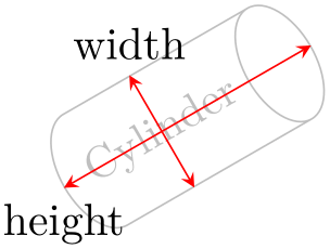
                    \usetikzlibrary {shapes.geometric}

                    \begin{tikzpicture}[>=stealth]

                      \node [cylinder, gray!50, rotate=30, draw,

                        minimum height=2cm, minimum width=1cm] (c) {Cylinder};

                      \draw[red, <->] (c.top)   --
                    (c.bottom)

                        node
                    [at end, below, black]   {height};

                      \draw[red, <->] (c.north) --
                    (c.south)

                        node
                    [at start, above, black] {width};

                    \end{tikzpicture}
Enlarging the shape to some minimum height will stretch only the body of the cylinder. By contrast, enlarging the shape to some minimum width will stretch the curved ends.

                    \usetikzlibrary {shapes.geometric}

                    \begin{tikzpicture}[shape aspect=.5]

                      \tikzset{every node/.style={cylinder, shape border rotate=90, draw}}

                      \node [minimum height=1.5cm]            {A};

                      \node [minimum width=1.5cm]  at
                    (1.5,0) {B};

                    \end{tikzpicture}
There are various keys to customize this shape (to use pgf keys in TikZ, simply remove the /pgf/ path).
The aspect is a recommendation for the quotient of the radii of the cylinder end. This may be ignored if the shape is enlarged to some minimum width.

                        \usetikzlibrary {shapes.geometric}

                        \begin{tikzpicture}[]

                          \tikzset{every node/.style={cylinder, shape border rotate=90, draw}}

                          \node [aspect=1.0]           {A};

                          \node [aspect=0.5]  at
                        (1,0) {B};

                          \node [aspect=0.25] at
                        (2,0) {C};

                        \end{tikzpicture}
This enables the use of a custom fill for the body and the end of the cylinder. The background path for the shape should not be filled (e.g., in TikZ, the fill option for the node must be implicitly or explicitly set to none). Internally, this key sets the TeX-if \ifpgfcylinderusescustomfill appropriately.

                    \usetikzlibrary {shapes.geometric}

                    \begin{tikzpicture}[aspect=0.5]

                      \node [cylinder, cylinder uses custom fill, cylinder end fill=red!50,

                             cylinder body fill=red!25] {Cylinder};

                    \end{tikzpicture}
Sets the color for the end of the cylinder.
Sets the color for the body of the cylinder.
The anchors of this shape are shown below (anchor 160 is an example of a border anchor). Note that the cylinder shape does not distinguish between outer xsep and outer ysep. Only the larger of the two values is used for the shape. Note also the difference between the center and shape center anchors: center is the center of the cylinder body and also the center of rotation. The shape center is the center of the shape which includes the 2-dimensional representation of the cylinder top.
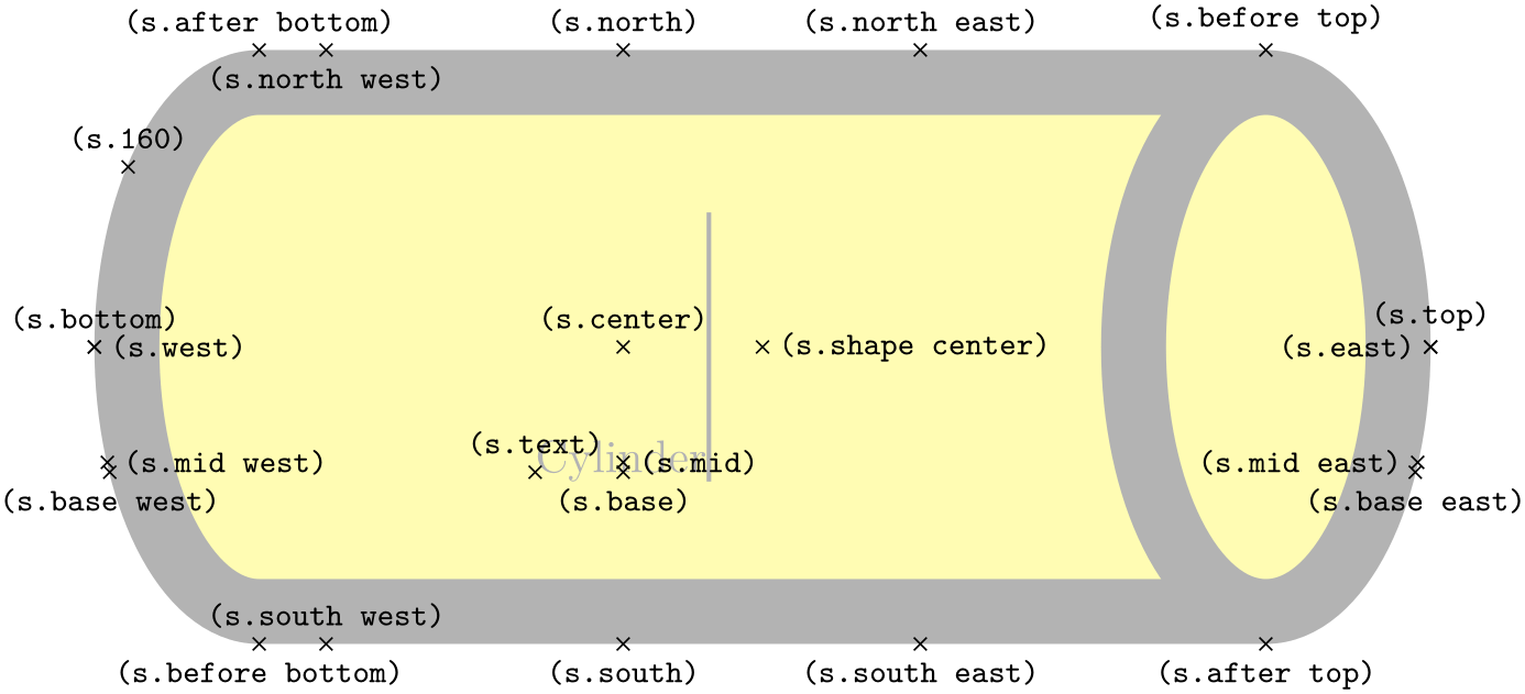
                    \usetikzlibrary {shapes.geometric}

                    \Huge

                    \begin{tikzpicture}

                      \node[name=s, shape=cylinder, shape example, aspect=.5, inner xsep=3cm,

                            inner ysep=1cm] {Cylinder\vrule width
                    1pt
                    height
                    2cm};

                      \foreach \anchor/\placement in

                        {before
                    top/above,    top/above,       after
                    top/below,

                         before
                    bottom/below, bottom/above,    after
                    bottom/above,

                         mid/right,           mid
                    west/right,  mid
                    east/left,

                         base/below,          base
                    west/below, base
                    east/below,

                         center/above,        text/above,      shape
                    center/right,

                         west/right, east/left, north/above, south/below,

                         north
                    west/below, north
                    east/above,

                         south
                    west/above, south
                    east/below, 160/above}

                      \draw[shift=(s.\anchor)] plot[mark=x] coordinates{(0,0)}

                        node[\placement] {\scriptsize\texttt{(s.\anchor)}};

                    \end{tikzpicture}
71.4 Symbol Shapes
-
TikZ Library shapes.symbols 
\usepgflibrary{shapes.symbols} %
LaTeX
and plain
TeX
and pure pgf
\usepgflibrary[shapes.symbols] % ConTeXt and pure pgf
\usetikzlibrary{shapes.symbols} %
LaTeX
and plain
TeX
when using TikZ
\usetikzlibrary[shapes.symbols] % ConTeXt when using TikZ
This library defines shapes that can be used for drawing symbols like a forbidden sign or a cloud.
-
Shape correct forbidden sign 
This shape places the node inside a circle with a diagonal from the upper left to the lower right added. The circle is part of the background, the diagonal line part of the foreground path; thus, the diagonal line is on top of the text.

                    \usetikzlibrary {shapes.symbols}

                    \begin{tikzpicture}

                      \node [correct forbidden sign,line width=1ex,draw=red,fill=white] {Smoking};

                    \end{tikzpicture}
The shape inherits all anchors from the circle shape.
-
Shape forbidden sign 
This shape is like correct forbidden sign, only the line goes from the lower left to the upper right. The strange naming of these shapes is for historical reasons.

                    \usetikzlibrary {shapes.symbols}

                    \begin{tikzpicture}

                      \node [forbidden sign,line width=1ex,draw=red,fill=white] {Smoking};

                    \end{tikzpicture}
The shape inherits all anchors from the circle shape.
-
Shape magnifying glass 
-
/pgf/magnifying glass handle angle=⟨degree⟩ (default -45) 
-
/pgf/magnifying glass handle aspect=⟨factor⟩ (default 1.5) 
This shape places the node inside a circle with a handle attached to the node. The angle of the handle and its length can be adjusted using two keys:
The angle of the handle.
The length of the handle as a multiple of the circle radius.

                    \usetikzlibrary {shapes.symbols}

                    \begin{tikzpicture}

                      \node [magnifying glass,line width=1ex,draw] {huge};

                    \end{tikzpicture}
The shape inherits all anchors from the circle shape.
-
Shape cloud 
-
/pgf/cloud puffs=⟨integer⟩ (no default, initially 10) 
-
/pgf/cloud puff arc=⟨angle⟩ (no default, initially 135) 
-
/pgf/cloud ignores aspect=⟨boolean⟩ (default true) 
This shape is a cloud, drawn to tightly fit the node contents (strictly speaking, using an ellipse which tightly fits the node contents – including any inner sep).

A cloud should be thought of as having a number of “puffs”, which are the individual arcs drawn around the border. There are pgf keys to specify how the cloud is drawn (to use these keys in TikZ, simply remove the /pgf/ path).
Sets the number of puffs for the cloud.
Sets the length of the puff arc (in degrees). A shorter arc can produce better looking joins between puffs for larger line widths.
Like the diamond shape, the cloud shape also uses the aspect key to determine the ratio of the width and the height of the cloud. However, there may be circumstances where it may be undesirable to continually specify the aspect for the cloud. Therefore, the following key is implemented:
Instruct pgf to ignore the aspect key. Internally, the TeX-if \ifpgfcloudignoresaspect is set appropriately. The initial value is false.

                        \usetikzlibrary {shapes.symbols}

                        \begin{tikzpicture}[aspect=1, every node/.style={cloud, cloud puffs=11, draw}]

                          \node [fill=gray!20]                                {rain};

                          \node [cloud ignores aspect, fill=white] at
                        (1.5,0) {snow};

                        \end{tikzpicture}
Any minimum size requirements are applied to the “circum-ellipse”, which is the ellipse which passes through all the midpoints of the puff arcs. These requirements are considered after any aspect specification is applied.
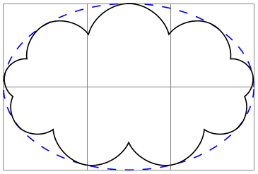
                    \usetikzlibrary {shapes.symbols}

                    \begin{tikzpicture}

                      \draw [help lines] grid
                    (3,2);

                      \draw [blue, dashed] (1.5, 1) ellipse
                    [x radius=1.5cm, y radius=1cm];

                      \node [cloud, cloud puffs=9, draw, minimum width=3cm, minimum height=2cm]

                        at
                    (1.5, 1) {};

                    \end{tikzpicture}
The anchors for the cloud shape are shown below for a cloud with eleven puffs. Anchor 70 is an example of a border anchor.
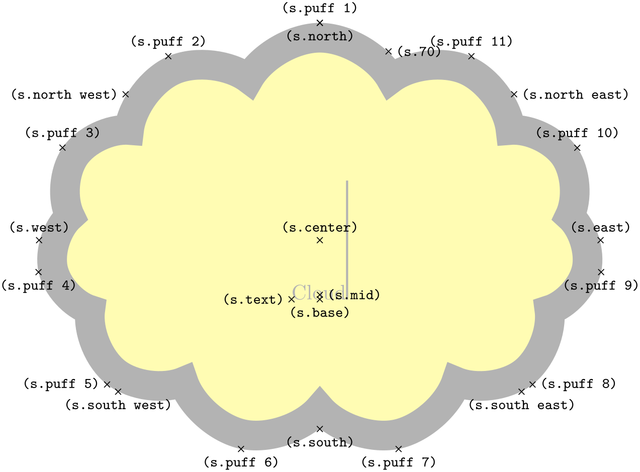
                    \usetikzlibrary {shapes.symbols}

                    \Huge

                    \begin{tikzpicture}

                      \node[name=s, shape=cloud, style=shape example, cloud puffs=11, aspect=1.5,

                           cloud puff arc=120,inner ysep=1cm] {Cloud\vrule width
                    1pt
                    height
                    2cm};

                      \foreach \anchor/\placement in

                       {puff
                    1/above, puff
                    2/above,  puff
                    3/above,  puff
                    4/below,

                        puff
                    5/left,  puff
                    6/below,  puff
                    7/below,  puff
                    8/right,

                        puff
                    9/below, puff
                    10/above, puff
                    11/above, 70/right,

                        center/above, base/below,    mid/right,     text/left,

                        north/below,  south/below,   east/above,    west/above,

                        north
                    west/left,             north
                    east/right,

                        south
                    west/below,            south
                    east/below}

                         \draw[shift=(s.\anchor)] plot[mark=x] coordinates{(0,0)}

                           node[\placement] {\scriptsize\texttt{(s.\anchor)}};

                    \end{tikzpicture}
-
Shape starburst 
-
/pgf/starburst points=⟨integer⟩ (no default, initially 17) 
-
/pgf/starburst point height=⟨length⟩ (no default, initially .5cm) 
-
/pgf/random starburst=⟨integer⟩ (no default, initially 100) 
This shape is a randomly generated elliptical star, which supports the rotation of the shape border as described in Section 17.2.3.

                    \usetikzlibrary {shapes.symbols}

                    \begin{tikzpicture}

                      \node[starburst, fill=yellow, draw=red, line width=2pt] {\bf BANG!};

                    \end{tikzpicture}
Like the star shape, the starburst should be thought of as having a set of inner points and outer points. The inner points lie on the ellipse which tightly fits the node contents (including any inner sep).
Using a specified ‘starburst point height’ value, the outer points are generated randomly between this value and one quarter of this value. For a given starburst shape, the angle between each point is fixed, and is determined by the number of points specified for the starburst.
It is important to note that, whilst the maximum possible point height is used to calculate minimum width or height requirements, the outer points are randomly generated, so there is (unfortunately) no guarantee that any such requirements will be fully met.

                    \usetikzlibrary {shapes.symbols}

                    \begin{tikzpicture}

                      \draw[help lines] grid(3,2);

                      \node[starburst, draw, minimum width=3cm, minimum height=2cm]

                        at
                    (1.5, 1) {\bf BOOM!};

                    \end{tikzpicture}
There are pgf keys to control the drawing of the starburst shape. To use these keys in TikZ, simply remove the /pgf/ path.
Sets the number of outer points for the starburst.
Sets the maximum distance between the inner point radius and the outer point radius.
Sets the seed for the random number generator for creating the starburst. The maximum value for ⟨integer⟩ is 16383. If ⟨integer⟩=0, the random number generator will not be used, and the maximum point height will be used for all outer points. If ⟨integer⟩ is omitted, a seed will be randomly chosen.
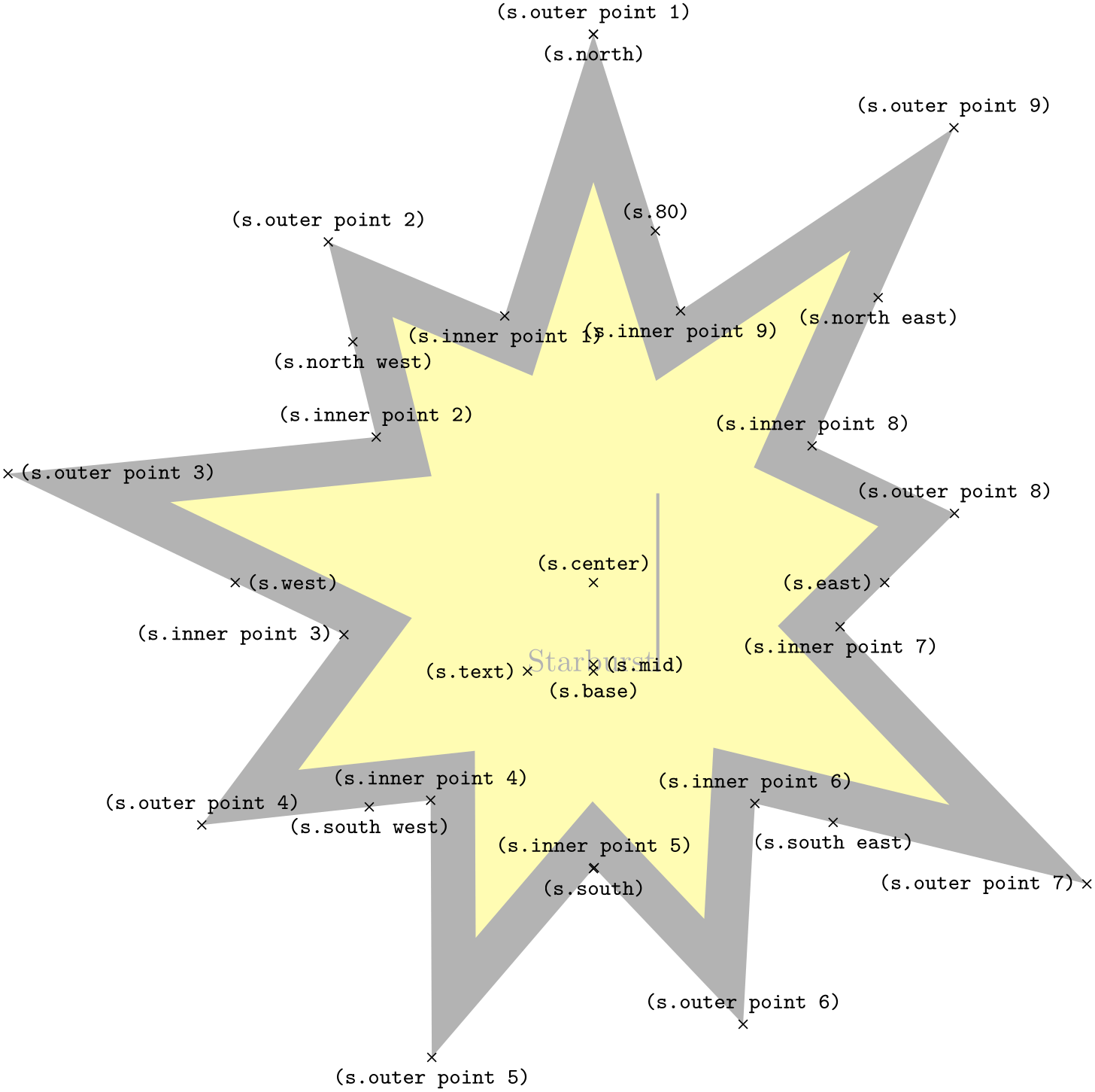
The basic anchors for a nine point starburst shape are shown below. Anchor 80 is an example of a border anchor.
                    \usetikzlibrary {shapes.symbols}

                    \Huge

                    \begin{tikzpicture}

                      \node[name=s, shape=starburst, starburst points=9, starburst point height=3.5cm,

                            style=shape example,inner sep=1cm]

                        {Starburst\vrule width
                    1pt
                    height
                    2cm};

                      \foreach \anchor/\placement in

                        {outer
                    point
                    1/above, outer
                    point
                    2/above, outer
                    point
                    3/right,

                         outer
                    point
                    4/above, outer
                    point
                    5/below, outer
                    point
                    6/above,

                         outer
                    point
                    7/left,  outer
                    point
                    8/above, outer
                    point
                    9/above,

                         inner
                    point
                    1/below, inner
                    point
                    2/above, inner
                    point
                    3/left,

                         inner
                    point
                    4/above, inner
                    point
                    5/above, inner
                    point
                    6/above,

                         inner
                    point
                    7/below, inner
                    point
                    8/above, inner
                    point
                    9/below,

                         center/above, text/left,   mid/right, base/below, 80/above,

                         north/below,  south/below, east/left, west/right,

                         north
                    east/below, south
                    west/below, south
                    east/below, north
                    west/below}

                      \draw[shift=(s.\anchor)] plot[mark=x] coordinates{(0,0)}

                        node[\placement] {\scriptsize\texttt{(s.\anchor)}};

                    \end{tikzpicture}
-
Shape signal 
-
/pgf/signal pointer angle=⟨angle⟩ (no default, initially 90) 
-
/pgf/signal from=⟨direction⟩ and ⟨opposite direction⟩ (no default, initially nowhere) 
-
/pgf/signal to=⟨direction⟩ and ⟨opposite direction⟩ (no default, initially east) 
This shape is a “signal” or sign shape, that is, a rectangle, with optionally pointed sides. A signal can point “to” somewhere, with outward points in that direction. It can also be “from” somewhere, with inward points from that direction. The resulting points extend the node contents (which include the inner sep).

                    \usetikzlibrary {shapes.symbols}

                    \begin{tikzpicture}

                      [every node/.style={signal, draw,  text=white, signal to=nowhere}]

                      \node[fill=green!65!black, signal to=east] at
                    (0,1) {To
                    East};

                      \node[fill=red!65!black, signal from=east] at
                    (0,0) {From
                    East};

                    \end{tikzpicture}
There are pgf keys for drawing the signal shape (to use these keys in TikZ, simply remove the /pgf/ path):
Sets the angle for the pointed sides of the shape. This angle is maintained when enforcing any minimum size requirements, so any adjustment to the width will affect the height, and vice versa.
Sets which sides take an inward pointer (i.e., that points towards the center of the shape). The possible values for ⟨direction⟩ and ⟨opposite direction⟩ are the compass point directions north, south, east and west (or above, below, right and left). An additional keyword nowhere can be used to reset the sides so they have no pointers. When used with signal from key, this only resets inward pointers; used with the signal to key, it only resets outward pointers.
Sets which sides take an outward pointer (i.e., that points away from the shape).
Note that pgf will ignore any instruction to use directions that are not opposites (so using the value east and north, will result in only north being assigned a pointer). This is also the case if non-opposite values are used in the signal to and signal from keys at the same time. So, for example, it is not possible for a signal to have an outward point to the left, and also have an inward point from below.
The anchors for the signal shape are shown below. Anchor 70 is an example of a border anchor.

                    \usetikzlibrary {shapes.symbols}

                    \Huge

                    \begin{tikzpicture}

                      \node[name=s, shape=signal, signal from=west, shape example, inner sep=2cm]

                        {Signal\vrule width1pt
                    height2cm};

                      \foreach \anchor/\placement in

                        {text/left,   center/above,    70/above,

                         base/below,  base
                    east/below, base
                    west/below,

                         mid/right,   mid
                    east/above
                    left,  mid
                    west/above
                    left,

                         north/above,      south/below,

                         east/above,       west/above,

                         north
                    west/above, north
                    east/above,

                         south
                    west/below, south
                    east/below}

                         \draw[shift=(s.\anchor)] plot[mark=x] coordinates{(0,0)}

                           node[\placement] {\scriptsize\texttt{(s.\anchor)}};

                    \end{tikzpicture}
-
Shape tape 
-
/pgf/tape bend top=⟨bend style⟩ (no default, initially in and out) 
-
/pgf/tape bend bottom=⟨bend style⟩ (no default, initially in and out) 
-
/pgf/tape bend height=⟨length⟩ (no default, initially 5pt) 
This shape is a rectangle with optional, “bendy” top and bottom sides, which tightly fits the node contents (including the inner sep).

                    \usetikzlibrary {shapes.symbols}

                    \begin{tikzpicture}

                      \node[tape, draw]{ABCD};

                      \node[tape, draw, tape bend top=none] at
                    (1.5, 0) {EFGH};

                    \end{tikzpicture}
There are pgf keys to specify which sides bend and how high the bends are (to use these keys in TikZ, simply remove the /pgf/ path):
Specifies how the top side bends. The ⟨bend style⟩ is either in and out, out and in or none (i.e., a straight line). The bending sides are drawn in a clockwise direction, and using the bend style in and out will mean the side will first bend inwards and then bend outwards. The opposite holds true for out and in.

                        \usetikzlibrary {shapes.symbols}

                        \begin{tikzpicture}[-stealth]

                          \node[tape, draw, gray, minimum width=2cm](t){Tape};

                          \draw [blue]([yshift=5pt] t.north west) --
                        ([yshift=5pt]t.north east)

                                 node[midway, above, black]{in
                        and
                        out};

                          \draw [blue]([yshift=-5pt]t.south east) --
                        ([yshift=-5pt]t.south west)

                                 node[sloped, allow upside down, midway, above, black]{in
                        and
                        out};

                        \end{tikzpicture}
This might take a bit of getting used to, but just remember that when you want the bendy sides to be parallel, the sides take the same bend style. It is possible for the top and bottom sides to take opposite bend styles, but the author of this shape cannot think of a single use for such a combination.

                        \usetikzlibrary {shapes.symbols}

                        \begin{tikzpicture}[every node/.style={tape, draw}]

                          \node [tape bend top=out and
                          in, tape bend bottom=out and
                          in] {Parallel};

                          \node at
                        (2,0) [tape bend bottom=out and
                          in]                  {Why?};

                        \end{tikzpicture}
Specifies how the bottom side bends.
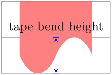
Sets the total height for a side with a bend.
                        \usetikzlibrary {shapes.symbols}

                        \begin{tikzpicture}[>=stealth]

                          \draw [help lines] grid(3,2);

                          \node [tape, fill, minimum size=2cm, red!50, tape bend top=none,

                                 tape bend height=1cm] at
                        (1.5,1.5) (t) {};

                          \draw [|<->|, blue] (1.5,0) --
                        (1.5,1)

                                 node
                        [at end, above, black]{tape
                        bend
                        height};

                        \end{tikzpicture}
The anchors for the tape shape are shown below. Anchor 60 is an example of a border anchor. Note that border anchors will snap to the center of convex curves (i.e. when bending in).

                    \usetikzlibrary {shapes.symbols}

                    \Huge

                    \begin{tikzpicture}

                      \node[name=s, shape=tape, tape bend height=1cm, shape example, inner xsep=3cm]

                        {Tape\vrule width1pt
                    height2cm};

                       \foreach \anchor/\placement in

                        {text/left,  center/above,    60/above,

                         base/below, base
                    east/below, base
                    west/below,

                         mid/right,  mid
                    east/left,   mid
                    west/right,

                         north/above, south/below,  east/above, west/above,

                         north
                    west/above, north
                    east/above,

                         south
                    west/below, south
                    east/below}

                         \draw[shift=(s.\anchor)] plot[mark=x] coordinates{(0,0)}

                           node[\placement] {\scriptsize\texttt{(s.\anchor)}};

                    \end{tikzpicture}
-
Shape magnetic tape 
-
/pgf/magnetic tape tail extend=⟨distance⟩ (no default, initially 0cm) 
-
/pgf/magnetic tape tail=⟨proportion⟩ (no default, initially 0.15) 
This shape represents a ‘magnetic tape’ or any sequential data store that is sometimes used in flowcharts. It is essentially a circle with a little tail:

                    \usetikzlibrary {shapes.symbols}

                    \tikz\node [magnetic tape, draw] (A) {A};
The following keys can be used to customise the magnetic tape shape:
This key sets how far the tail extends beyond the radius of the tape. Negative values will be ignored.

                        \usetikzlibrary {shapes.symbols}

                        \begin{tikzpicture}[every node/.style={magnetic tape, draw}]

                          \node [magnetic tape tail extend=0cm]    at
                        (0,0) {A};

                          \node [magnetic tape tail extend=0.25cm] at
                        (0,1) {B};

                        \end{tikzpicture}
This key sets the thickness of the ‘tail’ to be ⟨proportion⟩ times the radius of the shape. The ⟨proportion⟩ should be between 0.0 and 1.0.

                        \usetikzlibrary {shapes.symbols}

                        \begin{tikzpicture}[every node/.style={magnetic tape, draw}]

                          \node [magnetic tape tail=0.5, magnetic tape tail extend=0.5cm] {A};

                          \node [magnetic tape tail=0.25] at
                        (0,1) {B};

                        \end{tikzpicture}
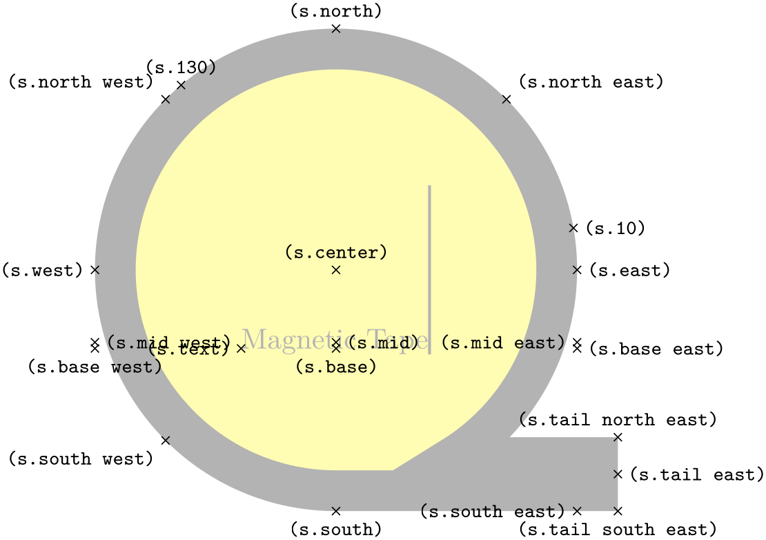
The following figure shows the anchors this shape defines; the anchors 10 and 130 are example of border anchors.
                    \usetikzlibrary {shapes.symbols}

                    \Huge

                    \begin{tikzpicture}

                    \node[name=s,shape=magnetic tape,shape example,inner sep=0.75cm,

                    magnetic tape tail extend=0.5cm]

                      {Magnetic
                    Tape\vrule width
                    1pt
                    height
                    2cm};

                    \foreach \anchor/\placement in

                      {north
                    west/above
                    left, north/above, north
                    east/above
                    right,

                      west/left, center/above, east/right,

                      mid
                    west/right, mid/right, mid
                    east/left,

                      base
                    west/below, base/below, base
                    east/right,

                      south
                    west/below
                    left, south/below, south
                    east/left,

                      text/left, 10/right, 130/above,

                      tail
                    east/right, tail
                    south
                    east/below, tail
                    north
                    east/above}

                        \draw[shift=(s.\anchor)] plot[mark=x] coordinates{(0,0)}

                          node[\placement] {\scriptsize\texttt{(s.\anchor)}};

                    \end{tikzpicture}
71.5 Arrow Shapes
-
TikZ Library shapes.arrows 
\usepgflibrary{shapes.arrows} %
LaTeX
and plain
TeX
and pure pgf
\usepgflibrary[shapes.arrows] % ConTeXt and pure pgf
\usetikzlibrary{shapes.arrows} %
LaTeX
and plain
TeX
when using TikZ
\usetikzlibrary[shapes.arrows] % ConTeXt when using TikZ
This library defines arrow shapes. Note that an arrow shape is something quite different from a (normal) arrow tip: It is a
shape that just “happens” to “look like” an arrow. In particular, you cannot use these shapes as
arrow tips.
-
Shape single arrow 
-
/pgf/single arrow tip angle=⟨angle⟩ (no default, initially 90) 
-
/pgf/single arrow head extend=⟨length⟩ (no default, initially .5cm) 
-
/pgf/single arrow head indent=⟨length⟩ (no default, initially 0cm) 
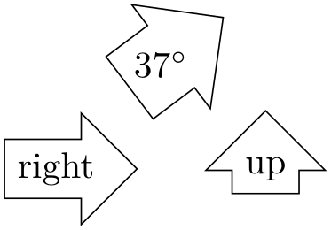
This shape is an arrow, which tightly fits the node contents (including any inner sep). This shape supports the rotation of the shape border, as described in Section 17.2.3. The angle of rotation determines in which direction the arrow points (provided no other rotational transformations are applied).
                    \usetikzlibrary {shapes.arrows}

                    \begin{tikzpicture}[every node/.style={single arrow, draw},

                        rotate border/.style={shape border uses incircle, shape border rotate=#1}]

                      \node {right};

                      \node at
                    (2,0) [shape border rotate=90]{up};

                      \node at
                    (1,1) [rotate border=37, inner sep=0pt]{$37^\circ$};

                    \end{tikzpicture}
Regardless of the rotation of the arrow border, the width is measured between the back ends of the arrow head, and the height is measured from the arrow tip to the end of the arrow tail.

                    \usetikzlibrary {shapes.arrows}

                    \begin{tikzpicture}[>=stealth,

                        rotate border/.style={shape border uses incircle, shape border rotate=#1}]

                      \node[rotate border=-30, fill=gray!25, minimum height=3cm, single arrow,

                        single arrow head extend=.5cm, single arrow head indent=.25cm] (arrow) {};

                      \draw[red, <->] (arrow.before tip) --
                    (arrow.after tip)

                        node
                    [near end, left, black] {width};

                      \draw[red, <->] (arrow.tip) --
                    (arrow.tail)

                        node
                    [near end, below left, black] {height};

                    \end{tikzpicture}
There are pgf keys that can be used to customize this shape (to use these keys in TikZ, simply remove the /pgf/ path).
Sets the angle for the arrow tip. Enlarging the arrow to some minimum width may increase the height of the shape to maintain this angle.
This sets the distance between the tail of the arrow and the outer end of the arrow head. This may change if the shape is enlarged to some minimum width.

                        \usetikzlibrary {shapes.arrows}

                        \begin{tikzpicture}

                          \node[single arrow, draw, single arrow head extend=.5cm, gray!50, rotate=60]

                             (a) {Arrow};

                          \draw[red, |<->|] (a.before tip) --
                        (a.before head)

                            node
                        [midway, below, sloped, black] {head
                        extend};

                        \end{tikzpicture}
This moves the point where the arrow head joins the shaft of the arrow towards the arrow tip, by ⟨length⟩.

                        \usetikzlibrary {shapes.arrows}

                        \begin{tikzpicture}[every node/.style={single arrow, draw=none, rotate=60}]

                          \node [fill=red!50]                                           {arrow
                        1};

                          \node [fill=blue!50, single arrow head indent=1ex] at
                        (1.5,0) {arrow
                        2};

                        \end{tikzpicture}
The anchors for this shape are shown below (anchor 20 is an example of a border anchor).
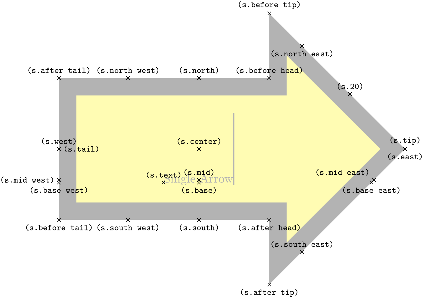
                    \usetikzlibrary {shapes.arrows}

                    \Huge

                    \begin{tikzpicture}

                      \node[name=s,shape=single arrow, shape example, single arrow head extend=1.5cm]

                        {Single
                    Arrow\vrule width1pt
                    height2cm};

                      \foreach \anchor/\placement in

                        {text/above,      center/above, 20/above,

                         mid
                    west/left,   mid/above,    mid
                    east/above
                    left,

                         base
                    west/below, base/below,   base
                    east/below,

                         tip/above, before
                    tip/above, after
                    tip/below, before
                    head/above,

                         after
                    head/below, after
                    tail/above, before
                    tail/below, tail/right,

                         north/above, south/below, east/below, west/above,

                         north
                    west/above, north
                    east/below, south
                    west/below, south
                    east/above}

                         \draw[shift=(s.\anchor)] plot[mark=x] coordinates{(0,0)}

                           node[\placement] {\scriptsize\texttt{(s.\anchor)}};

                    \end{tikzpicture}
-
Shape double arrow 
-
/pgf/double arrow tip angle=⟨angle⟩ (no default, initially 90) 
-
/pgf/double arrow head extend=⟨length⟩ (no default, initially .5cm) 
-
/pgf/double arrow head indent=⟨length⟩ (no default, initially 0cm) 
This shape is a double arrow, which tightly fits the node contents (including any inner sep), and supports the rotation of the shape border, as described in Section 17.2.3.

                    \usetikzlibrary {shapes.arrows}

                    \begin{tikzpicture}[every node/.style={double arrow, draw}]

                      \node [double arrow, draw] {Left
                    or
                    Right};

                    \end{tikzpicture}
The double arrow behaves exactly like the single arrow, so you need to remember that the width is always the distance between the back ends of the arrow heads, and the height is always the tip-to-tip distance.
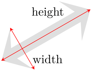
                    \usetikzlibrary {shapes.arrows}

                    \begin{tikzpicture}[>=stealth,

                        rotate border/.style={shape border uses incircle, shape border rotate=#1}]

                      \node[rotate border=210, fill=gray!25, minimum height=3cm, double arrow,

                        double arrow head extend=.5cm, double arrow head indent=.25cm] (arrow) {};

                      \draw[red, <->] (arrow.before tip 1) --
                    (arrow.after tip 1)

                        node
                    [near start, right, black] {width};

                      \draw[red, <->] (arrow.tip 1) --
                    (arrow.tip 2)

                        node
                    [near end, above left, black] {height};

                    \end{tikzpicture}
The pgf keys that can be used to customize the double arrow behave similarly to the keys for the single arrow (to use these keys in TikZ, simply remove the /pgf/ path).
Sets the angle for the arrow tip. Enlarging the arrow to some minimum width may increase the height of the shape to maintain this angle.
This sets the distance between the shaft of the arrow and the outer end of the arrow heads. This may change if the shape is enlarged to some minimum width.
This moves the point where the arrow heads join the shaft of the arrow towards the arrow tips, by ⟨length⟩.

                        \usetikzlibrary {shapes.arrows}

                        \begin{tikzpicture}[every node/.style={double arrow, draw=none, rotate=-60}]

                          \node [fill=red!50]                                           {arrow
                        1};

                          \node [fill=blue!50, double arrow head indent=1ex] at
                        (1.5,0) {arrow
                        2};

                        \end{tikzpicture}
The anchors for this shape are shown below (anchor 20 is an example of a border anchor).
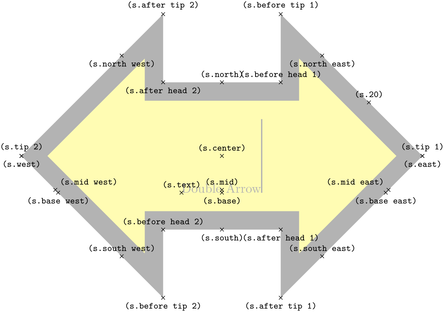
                    \usetikzlibrary {shapes.arrows}

                    \Huge

                    \begin{tikzpicture}

                      \node[name=s,shape=double arrow, double arrow head extend=1.5cm, shape example, inner xsep=2cm]

                        {Double
                    Arrow\vrule width1pt
                    height2cm};

                      \foreach \anchor/\placement in

                        {text/above, center/above, 20/above,

                         mid
                    west/above
                    right, mid/above, mid
                    east/above
                    left,

                         base
                    west/below, base/below, base
                    east/below,

                         before
                    head
                    1/above, before
                    tip
                    1/above, tip
                    1/above, after
                    tip
                    1/below, after
                    head
                    1/below,

                         before
                    head
                    2/above, before
                    tip
                    2/below, tip
                    2/above, after
                    tip
                    2/above, after
                    head
                    2/below,

                         north/above, south/below, east/below, west/below,

                         north
                    west/below, north
                    east/below, south
                    west/above, south
                    east/above}

                         \draw[shift=(s.\anchor)] plot[mark=x] coordinates{(0,0)}

                           node[\placement] {\scriptsize\texttt{(s.\anchor)}};

                    \end{tikzpicture}
-
Shape arrow box 
-
/pgf/arrow box tip angle=⟨angle⟩ (no default, initially 90) 
-
/pgf/arrow box head extend=⟨length⟩ (no default, initially .125cm) 
-
/pgf/arrow box head indent=⟨length⟩ (no default, initially 0cm) 
-
/pgf/arrow box shaft width=⟨length⟩ (no default, initially .125cm) 
-
/pgf/arrow box north arrow=⟨distance⟩ (no default, initially .5cm) 
-
/pgf/arrow box south arrow=⟨distance⟩ (no default, initially .5cm) 
-
/pgf/arrow box east arrow=⟨distance⟩ (no default, initially .5cm) 
-
/pgf/arrow box west arrow=⟨distance⟩ (no default, initially .5cm) 
-
/pgf/arrow box arrows={⟨list⟩}(no default) 
This shape is a rectangle with optional arrows which extend from the four sides.

                    \usetikzlibrary {shapes.arrows}

                    \begin{tikzpicture}

                      \node[arrow box, draw] {A};

                      \node[arrow box, draw, arrow box arrows={north:.5cm, west:0.75cm}]

                        at
                    (2,0) {B};

                    \end{tikzpicture}
Any minimum size requirements are applied to the main rectangle only. This does not pose too many problems if you wish to accommodate the length of the arrows, as it is possible to specify the length of each arrow independently, from either the border of the rectangle (the default) or the center of the rectangle.
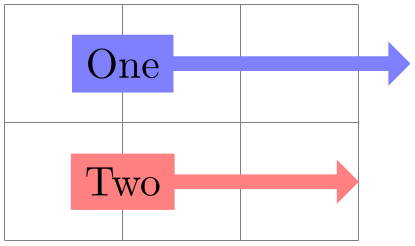
                    \usetikzlibrary {shapes.arrows}

                    \begin{tikzpicture}

                        \tikzset{box/.style={arrow box, fill=#1}}

                        \draw [help lines] grid(3,2);

                      \node[box=blue!50, arrow box arrows={east:2cm}]             at
                    (1,1.5){One};

                      \node[box=red!50,  arrow box arrows={east:2cm from center}] at
                    (1,0.5){Two};

                    \end{tikzpicture}
There are various pgf keys for drawing this shape (to use these keys in TikZ, simply remove the /pgf/ path).
Sets the angle at the arrow tip for all four arrows.
Sets the distance the arrow head extends away from the shaft of the arrow. This applies to all arrows.
Moves the point where the arrow head joins the shaft of the arrow towards the arrow tip. This applies to all arrows.
Sets the width of the shaft of all arrows.
Sets the distance the north arrow extends from the node. By default this is from the border of the shape, but by using the additional keyword from center, the distance will be measured from the center of the shape. If ⟨distance⟩ is 0pt or a negative distance, the arrow will not be drawn.
Sets the distance the south arrow extends from the node.
Sets the distance the east arrow extends from the node.
Sets the distance the west arrow extends from the node.
Sets the distance that all arrows extend from the node. The specification in ⟨list⟩ consists of the four compass points north, south, east or west, separated by commas (so the list must be contained within braces). The distances can be specified after each side separated by a colon (e.g., north:1cm, or west:5cm from center). If an item specifies no distance, the most recently specified distance will be used (at the start of the list this is 0cm, so the first item in the list should specify a distance). Any sides not specified will not be drawn with an arrow.
The anchors for this shape are shown below (unfortunately, due to its size, this example must be rotated). Anchor 75 is an example of a border anchor. If a side is drawn without an arrow, the anchors for that arrow should be considered unavailable. They are (unavoidably) defined, but default to the center of the appropriate side.

                    \usetikzlibrary {shapes.arrows}

                    \Huge

                    \begin{tikzpicture}

                      \node[shape=arrow box, shape example, inner xsep=1cm, inner ysep=1.5cm, arrow box shaft width=2cm,

                        arrow box arrows={north:3.5cm from border, south, east:5cm from border, west},

                        arrow box head extend=0.75cm, rotate=-90](s) {Arrow
                    Box\vrule width1pt
                    height2cm};

                      \foreach \anchor/\placement in

                       {center/above, text/above, mid/right, base/below, 75/above,

                        mid
                    east/right, mid
                    west/left, base
                    east/right, base
                    west/left,

                        north/below, south/below, east/below, west/below,

                        north
                    east/above, south
                    east/above, south
                    west/below, north
                    west/below,

                        north
                    arrow
                    tip/above,south
                    arrow
                    tip/above, east
                    arrow
                    tip/above, west
                    arrow
                    tip/above,

                        before
                    north
                    arrow/above, before
                    north arrow
                    head/below
                    left, before
                    north arrow
                    tip/above
                    left,

                        after
                    north arrow
                    tip/above
                    right, after
                    north arrow
                    head/below
                    right, after
                    north
                    arrow/below,

                        before
                    south
                    arrow/below, before
                    south arrow
                    head/above
                    right, before
                    south arrow
                    tip/below
                    right,

                        after
                    south arrow
                    tip/below
                    left, after
                    south arrow
                    head/above
                    left, after
                    south
                    arrow/above,

                        before
                    east
                    arrow/above, before
                    east arrow
                    head/above
                    right, before
                    east arrow
                    tip/above,

                        after
                    east arrow
                    tip/below, after
                    east arrow
                    head/below
                    right, after
                    east
                    arrow/below,

                        before
                    west
                    arrow/below, before
                    west arrow
                    head/below
                    left, before
                    west arrow
                    tip/below,

                        after
                    west arrow
                    tip/above, after
                    west arrow
                    head/above
                    left, after
                    west
                    arrow/below}

                          \draw[shift=(s.\anchor)] plot[mark=x] coordinates{(0,0)}

                            node[\placement, rotate=-90] {\scriptsize\texttt{(s.\anchor)}};

                    \end{tikzpicture}
71.6 Shapes with Multiple Text Parts
-
TikZ Library shapes.multipart 
\usepgflibrary{shapes.multipart} %
LaTeX
and plain
TeX
and pure pgf
\usepgflibrary[shapes.multipart] % ConTeXt and pure pgf
\usetikzlibrary{shapes.multipart} %
LaTeX
and plain
TeX
when using TikZ
\usetikzlibrary[shapes.multipart] % ConTeXt when using TikZ
This library defines general-purpose shapes that are composed of multiple (text) parts.
-
Shape circle split 
This shape is a multi-part shape consisting of a circle with a line in the middle. The upper part is the main part (the text part), the lower part is the lower part.
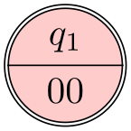
                    \usetikzlibrary {shapes.multipart}

                    \begin{tikzpicture}

                      \node [circle split,draw,double,fill=red!20]

                      {

                        $q_1$

                        \nodepart{lower}

                        $00$

                      };

                    \end{tikzpicture}
The shape inherits all anchors from the circle shape and defines the lower anchor in addition. See also the following figure:
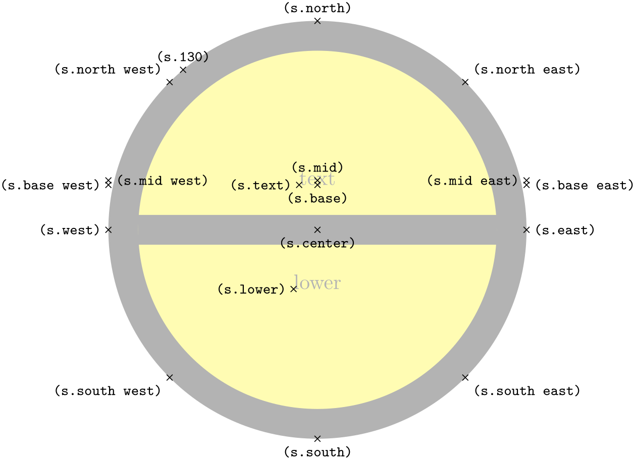
                    \usetikzlibrary {shapes.multipart}

                    \Huge

                    \begin{tikzpicture}

                      \node[name=s,shape=circle split,shape example] {text\nodepart{lower}lower};

                      \foreach \anchor/\placement in

                        {north
                    west/above
                    left, north/above, north
                    east/above
                    right,

                         west/left, center/below, east/right,

                         mid
                    west/right, mid/above, mid
                    east/left,

                         base
                    west/left, base/below, base
                    east/right,

                         south
                    west/below
                    left, south/below, south
                    east/below
                    right,

                         text/left, lower/left, 130/above}

                         \draw[shift=(s.\anchor)] plot[mark=x] coordinates{(0,0)}

                           node[\placement] {\scriptsize\texttt{(s.\anchor)}};

                    \end{tikzpicture}
-
Shape circle solidus 
This shape (due to Manuel Lacruz) is similar to the split circle, but the two text parts are arranged diagonally.

                    \usetikzlibrary {shapes.multipart}

                    \begin{tikzpicture}

                      \node [circle solidus,draw,double,fill=red!20]

                      {

                        $q_1$

                        \nodepart{lower}

                        $00$

                      };

                    \end{tikzpicture}
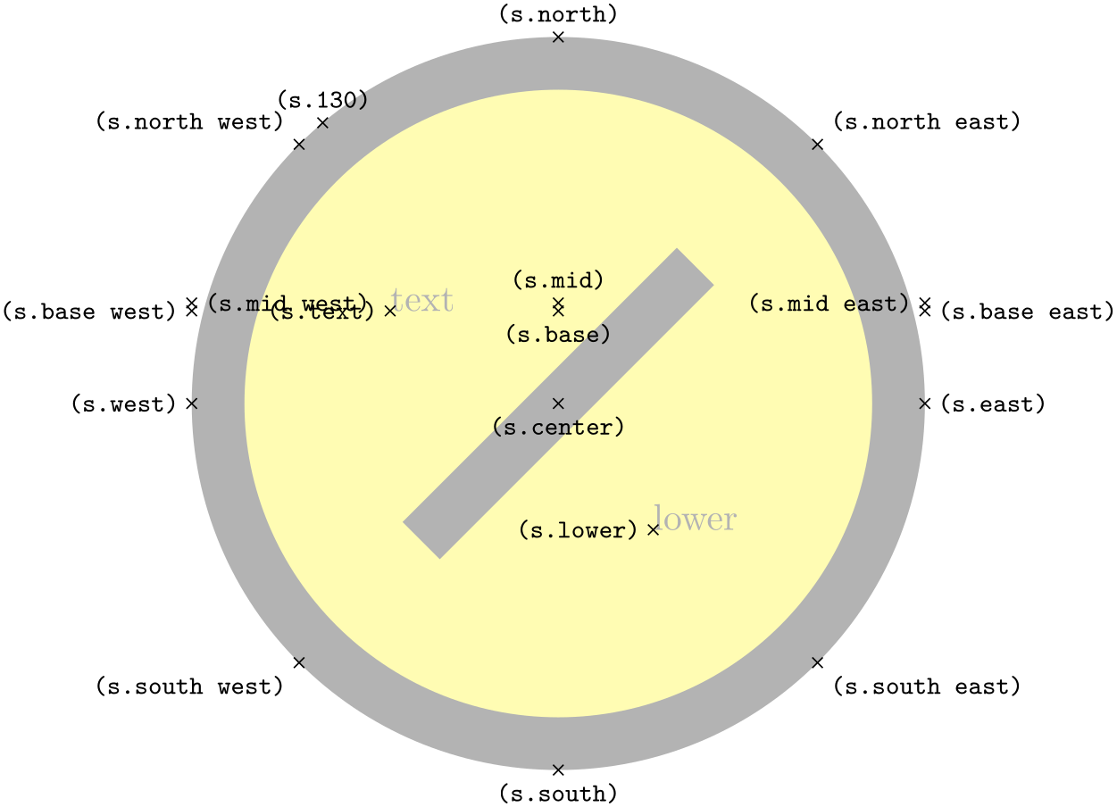
                    \usetikzlibrary {shapes.multipart}

                    \Huge

                    \begin{tikzpicture}

                      \node[name=s,shape=circle solidus,shape example,inner xsep=1cm] {text\nodepart{lower}lower};

                      \foreach \anchor/\placement in

                        {north
                    west/above
                    left, north/above, north
                    east/above
                    right,

                         west/left, center/below, east/right,

                         mid
                    west/right, mid/above, mid
                    east/left,

                         base
                    west/left, base/below, base
                    east/right,

                         south
                    west/below
                    left, south/below, south
                    east/below
                    right,

                         text/left, lower/left, 130/above}

                         \draw[shift=(s.\anchor)] plot[mark=x] coordinates{(0,0)}

                           node[\placement] {\scriptsize\texttt{(s.\anchor)}};

                    \end{tikzpicture}
-
Shape ellipse split 
This shape is a multi-part shape consisting of an ellipse with a line in the middle. The upper part is the main part (the text part), the lower part is the lower part. The anchors for this shape are shown below. Anchor 60 is a border anchor.
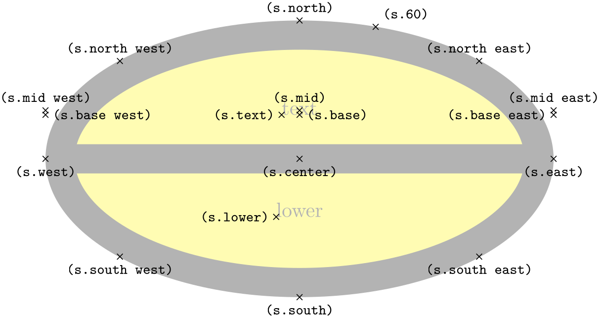
                    \usetikzlibrary {shapes.multipart}

                    \Huge

                    \begin{tikzpicture}

                      \node[name=s,shape=ellipse split,shape example] {text\nodepart{lower}lower};

                      \foreach \anchor/\placement in

                        {center/below, text/left, lower/left, 60/above
                    right,

                         mid/above, mid
                    east/above, mid
                    west/above,

                         base/right, base
                    east/left, base
                    west/right,

                         north/above, south/below, east/below, west/below,

                         north
                    east/above, south
                    east/below, south
                    west/below, north
                    west/above}

                         \draw[shift=(s.\anchor)] plot[mark=x] coordinates{(0,0)}

                           node[\placement] {\scriptsize\texttt{(s.\anchor)}};

                    \end{tikzpicture}
-
Shape diamond split 
This shape is a multi-part shape consisting of a diamond with a line in the middle. The upper part is the main part (the text part); the lower part is the lower part.
                    \usetikzlibrary {shapes.multipart}

                    \Huge

                    \begin{tikzpicture}

                      \node[name=s,shape=diamond split,shape example,inner xsep=1cm] {text\nodepart{lower}lower};

                      \foreach \anchor/\placement in

                        {north
                    west/above
                    left, north/above, north
                    east/above
                    right,

                         west/left, center/below, east/right, mid/above, base/below,

                         south
                    west/below
                    left, south/below, south
                    east/below
                    right,

                         text/left, lower/left, 130/above}

                         \draw[shift=(s.\anchor)] plot[mark=x] coordinates{(0,0)}

                           node[\placement] {\scriptsize\texttt{(s.\anchor)}};

                    \end{tikzpicture}
-
Shape rectangle split 
-
/pgf/rectangle split allocate boxes=⟨number⟩(no default) 
-
/pgf/rectangle split parts=⟨number⟩ (no default, initially 4) 
-
/pgf/rectangle split horizontal=⟨boolean⟩ (default true) 
-
/pgf/rectangle split ignore empty parts=⟨boolean⟩ (default true) 
-
/pgf/rectangle split empty part width=⟨length⟩ (no default, initially 1ex) 
-
/pgf/rectangle split empty part height=⟨length⟩ (no default, initially 1ex) 
-
/pgf/rectangle split empty part depth=⟨length⟩ (no default, initially 0ex) 
-
/pgf/rectangle split part align={⟨list⟩} (no default, initially center) 
-
/pgf/rectangle split draw splits=⟨boolean⟩ (default true) 
-
/pgf/rectangle split use custom fill=⟨boolean⟩ (default true) 
-
/pgf/rectangle split part fill={⟨list⟩} (no default, initially white) 
This shape is a rectangle, which can be split either horizontally or vertically into several parts.

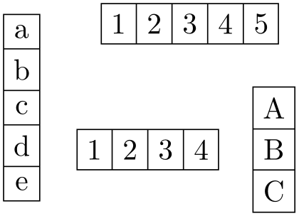
                    \usetikzlibrary {shapes.multipart}

                    \begin{tikzpicture}[my shape/.style={

                      rectangle split, rectangle split parts=#1, draw, anchor=center}]

                      \node [my shape=5] at
                    (0,1)

                        {a\nodepart{two}b\nodepart{three}c\nodepart{four}d\nodepart{five}e};

                      \node [my shape=5, rectangle split horizontal] at
                    (2,2)

                        {1\nodepart{two}2\nodepart{three}3\nodepart{four}4\nodepart{five}5};

                      \node [my shape=3] at
                    (3,0.5)

                        {A\nodepart{two}B\nodepart{three}C};

                      \node [my shape=4, rectangle split horizontal] at
                    (1.5,0.5)

                        {1\nodepart{two}2\nodepart{three}3\nodepart{four}4};

                    \end{tikzpicture}
The shape can be split into a maximum of twenty parts. However, to avoid allocating a lot of unnecessary boxes, pgf only allocates four boxes by default. To use the rectangle split shape with more than four boxes, the extra boxes must be allocated manually in advance (perhaps using \newbox or \let). The boxes take the form \pgfnodepart⟨number⟩box, where ⟨number⟩ is from the cardinal numbers one, two, three, … and so on. \pgfnodepartonebox is special in that it is synonymous with \pgfnodeparttextbox. For compatibility with earlier versions of this shape, the boxes \pgfnodeparttwobox, \pgfnodepartthreebox and \pgfnodepartfourbox, can be referred to using the ordinal numbers: \pgfnodepartsecondbox, \pgfnodepartthirdbox and \pgfnodepartfourthbox. In order to facilitate the allocation of these extra boxes, the following key is provided:
This key checks if ⟨number⟩ boxes have been allocated, and if not, it allocates the required boxes using \newbox (some “magic” is performed to get around the fact that \newbox is declared \outer in plain TeX).
When split vertically, the rectangle split will meet any minimum width requirements, but any minimum height will be ignored. Conversely when split horizontally, minimum height requirements will be met, but any minimum width will be ignored. In addition, inner sep is applied to every part that is used, so it cannot be specified independently for a particular part.
There are several pgf keys to specify how the shape is drawn. To use these keys in TikZ, simply remove the /pgf/ path:
Split the rectangle into ⟨number⟩ parts, which should be in the range 1 to 20. If more than four parts are needed, the boxes should be allocated in advance as described above.

                        \usetikzlibrary {shapes.multipart}

                        \begin{tikzpicture}[every text node part/.style={align=center}]

                          \node[rectangle split, rectangle split parts=3, draw, text width=2.75cm]

                            {Student

                             \nodepart{two}

                               age:int
                        \\

                               name:String

                             \nodepart{three}

                               getAge():int
                        \\

                               getName():String};

                        \end{tikzpicture}
This key determines whether the rectangle is split horizontally or vertically
When ⟨boolean⟩ is true, pgf will ignore any part that is empty except the text part. This effectively overrides the rectangle split parts key in that, if 3 parts (for example) are specified, but one is empty, only two will be shown.
                        \usetikzlibrary {shapes.multipart}

                        \begin{tikzpicture}[every node/.style={draw, anchor=text, rectangle split,

                            rectangle split parts=3}]

                          \node {text
                        \nodepart{second} \nodepart{third}third};

                          \node [rectangle split ignore empty parts] at
                        (2,0)

                                {text
                        \nodepart{second} \nodepart{third}third};

                        \end{tikzpicture}
Sets the default width for a node part box if it is empty and empty parts are not ignored.
Sets the default height for a node part box if it is empty and empty parts are not ignored.
Sets the default depth for a node part box if it is empty and empty parts are not ignored.
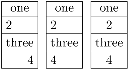
Sets the alignment of the boxes inside the node parts. Each item in ⟨list⟩ should be separated by commas (so if there is more than one item in ⟨list⟩, it must be surrounded by braces).
When the rectangle is split vertically, the entries in ⟨list⟩ must be one of left, right, or center. If ⟨list⟩ has less entries than node parts then the remaining boxes are aligned according to the last entry in the list. Note that this only aligns the boxes in each part and does not affect the alignment of the contents of the boxes.

                        \usetikzlibrary {shapes.multipart}

                        \def\x{one
                        \nodepart{two} 2
                        \nodepart{three} three
                        \nodepart{four} 4}

                        \begin{tikzpicture}[

                          every node/.style={rectangle split, rectangle split parts=4,

                            draw}

                          ]

                          \node[rectangle split part align={center, left, right}] at
                        (0,0)    {\x};

                          \node[rectangle split part align={center, left}]        at
                        (1.25,0) {\x};

                          \node[rectangle split part align={center}]              at
                        (2.5,0)  {\x};

                        \end{tikzpicture}
When the rectangle is split horizontally, the entries in ⟨list⟩ must be one of top, bottom, center or base. Note that using the value base will only make sense if all the node part boxes are being aligned in this way. This is because the base value aligns the boxes in relation to each other, whereas the other values align the boxes in relation to the part of the shape they occupy.
                        \usetikzlibrary {shapes.multipart}

                        \def\x{\Large w\nodepart{two}x\nodepart{three}\Huge y\nodepart{four}\tiny z}

                        \begin{tikzpicture}[

                          every node/.style={rectangle split, rectangle split parts=4,

                            draw, rectangle split horizontal}

                          ]

                          \node[rectangle split part align={center, top, bottom}] at
                        (0,0)     {\x};

                          \node[rectangle split part align={center, top}]         at
                        (0,-1.25) {\x};

                          \node[rectangle split part align={center}]              at
                        (0,-2.5)  {\x};

                          \node[rectangle split part align=base]                  at
                        (0,-3.75) {\x};

                        \end{tikzpicture}
Sets whether the line or lines between node parts will be drawn. Internally, this sets the TeX-if \ifpgfrectanglesplitdrawsplits appropriately.
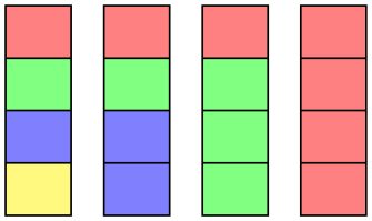
This enables the use of a custom fill for each of the node parts (including the area covered by the inner sep). The background path for the shape should not be filled (e.g., in TikZ, the fill option for the node must be implicitly or explicitly set to none). Internally, this key sets the TeX-if \ifpgfrectanglesplitusecustomfill appropriately.
Sets the custom fill color for each node part shape. The items in ⟨list⟩ should be separated by commas (so if there is more than one item in ⟨list⟩, it must be surrounded by braces). If ⟨list⟩ has less entries than node parts, then the remaining node parts use the color from the last entry in the list. This key will automatically set /pgf/rectangle split use custom fill.
                        \usetikzlibrary {shapes.multipart}

                        \begin{tikzpicture}

                          \tikzset{every node/.style={rectangle split, draw, minimum width=.5cm}}

                          \node[rectangle split part fill={red!50, green!50, blue!50, yellow!50}]  {};

                          \node[rectangle split part fill={red!50, green!50, blue!50}] at
                        (0.75,0) {};

                          \node[rectangle split part fill={red!50, green!50}]          at
                        (1.5,0)  {};

                          \node[rectangle split part fill={red!50}]                    at
                        (2.25,0) {};

                        \end{tikzpicture}
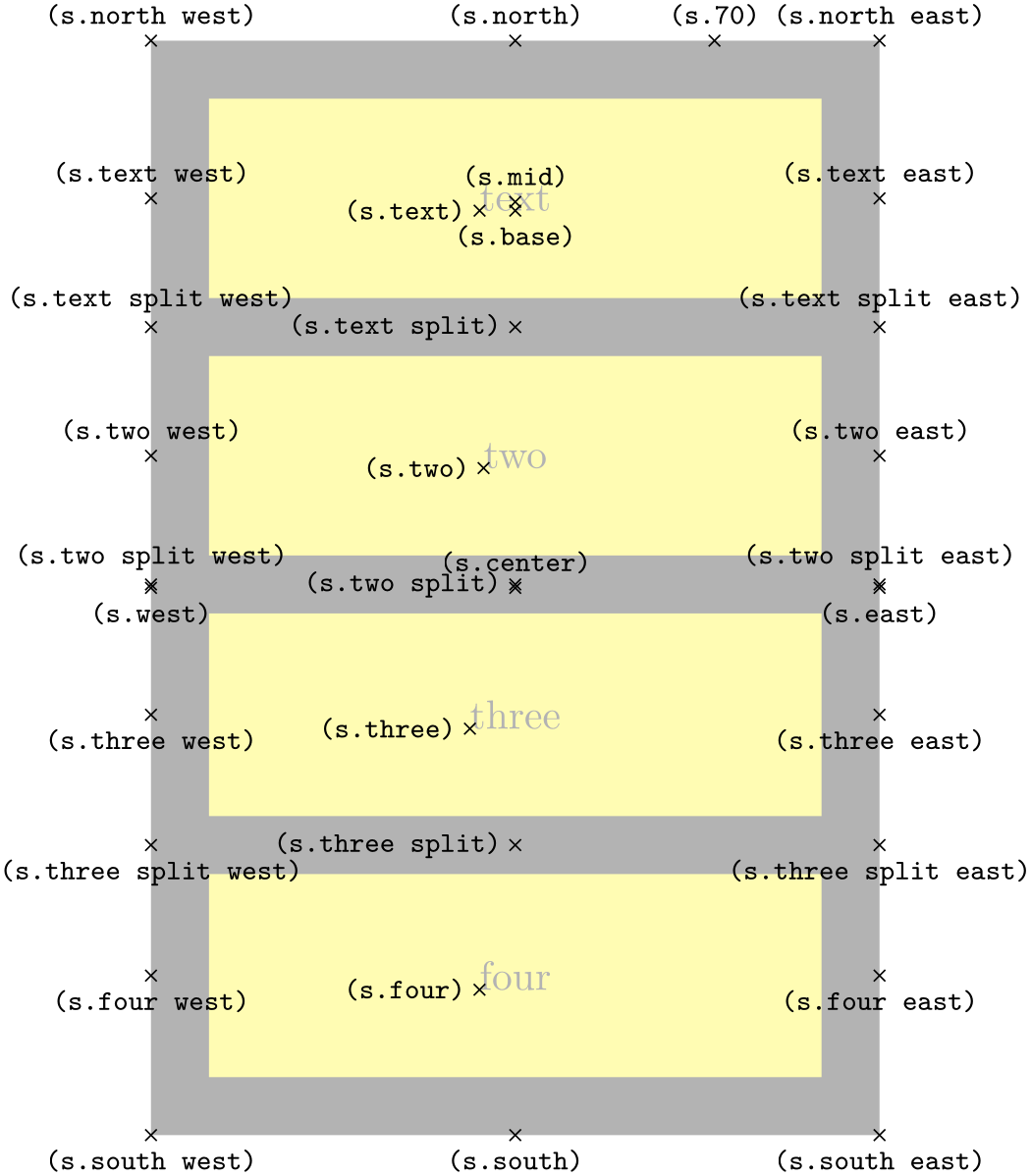
The anchors for the rectangle split shape split vertically into four, are shown below (anchor 70 is an example of a border angle). When a node part is missing, the anchors prefixed with the name of that node part should be considered unavailable. They are (unavoidably) defined, but default to other anchor positions.

                    \usetikzlibrary {shapes.multipart}

                    \Huge

                    \begin{tikzpicture}

                      \node[name=s,shape=rectangle split, rectangle split parts=4, shape example,

                        inner ysep=0.75cm]

                        {\nodepart{text}text\nodepart{two}two

                            \nodepart{three}three\nodepart{four}four};

                      \foreach \anchor/\placement in

                        {text/left, text
                    east/above, text
                    west/above,

                         two/left, two
                    east/above, two
                    west/above,

                         three/left, three
                    east/below, three
                    west/below,

                         four/left, four
                    east/below, four
                    west/below,

                         text
                    split/left, text
                    split
                    east/above, text
                    split
                    west/above,

                         two
                    split/left, two
                    split
                    east/above, two
                    split
                    west/above,

                         three
                    split/left, three
                    split
                    east/below, three
                    split
                    west/below,

                         north/above, south/below, east/below, west/below,

                         north
                    west/above, north
                    east/above, south
                    west/below, south
                    east/below,

                         center/above, 70/above, mid/above, base/below}

                         \draw[shift=(s.\anchor)] plot[mark=x] coordinates{(0,0)}

                           node[\placement] {\scriptsize\texttt{(s.\anchor)}};

                    \end{tikzpicture}
71.7 Callout Shapes
-
TikZ Library shapes.callouts 
\usepgflibrary{shapes.callouts} %
LaTeX
and plain
TeX
and pure pgf
\usepgflibrary[shapes.callouts] % ConTeXt and pure pgf
\usetikzlibrary{shapes.callouts} %
LaTeX
and plain
TeX
when using TikZ
\usetikzlibrary[shapes.callouts] % ConTeXt when using TikZ
Producing basic callouts can be done quite easily in pgf and
TikZ by creating a node and then subsequently drawing a path from the border of the node to
the required point. This library provides more fancy, ‘balloon’-style callouts.

Callouts consist of a main shape and a pointer (which is part of the shape) which points to something in (or outside) the picture. The position on the border of the main shape to which the pointer is connected is determined automatically. However, the pointer is ignored when calculating the minimum size of the shape, and also when positioning anchors.
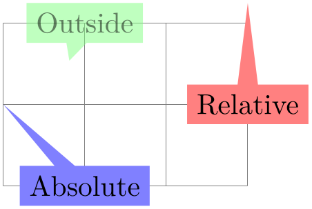
                \usetikzlibrary {shapes.callouts}

                \begin{tikzpicture}[remember picture]

                  \node[ellipse callout, draw] (hallo) {Hallo!};

                \end{tikzpicture}
There are two kinds of pointer: the “relative” pointer and the “absolute” pointer. The relative pointer calculates the angle of a specified coordinate relative to the center of the main shape, locates the point on the border to which this angle corresponds, and then adds the coordinate to this point. This seemingly over-complex approach means than you do not have to guess the size of the main shape: the relative pointer will always be outside. The absolute pointer, on the other hand, is much simpler: it points to the specified coordinate absolutely (and can even point to named coordinates in different pictures).
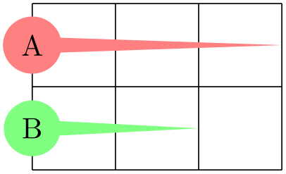
                \usetikzlibrary {shapes.callouts}

                \begin{tikzpicture}[remember picture, note/.style={rectangle callout, fill=#1}]

                  \draw [help lines] grid(3,2);

                  \node [note=red!50,  callout relative pointer={(0,1)}] at
                (3,1) {Relative};

                  \node [note=blue!50, callout absolute pointer={(0,1)}] at
                (1,0) {Absolute};

                  \node [note=green!50, opacity=.5, overlay,

                         callout absolute pointer={(hallo.south)}]       at
                (1,2) {Outside};

                \end{tikzpicture}
The following keys are common to all callouts. Please remember that the callout relative pointer, and callout absolute pointer keys take a different format for their value depending on whether they are being used in pgf or TikZ.
-
/pgf/callout relative pointer=⟨coordinate⟩ (no default, initially \pgfpointpolar{315}{.5cm}) 
Sets the vector of the callout pointer ‘relative’ to the callout shape.
-
/pgf/callout absolute pointer=⟨coordinate⟩(no default) 
Sets the vector of the callout pointer absolutely within the picture.
-
/tikz/callout relative pointer=⟨coordinate⟩ (no default, initially (315:.5cm)) 
The TikZ version of the callout relative pointer key. Here, ⟨coordinate⟩ can be specified using the TikZ format for coordinates.
-
/tikz/callout absolute pointer=⟨coordinate⟩(no default) 
The TikZ version of the callout absolute pointer key. Here, ⟨coordinate⟩ can be specified using the TikZ format for coordinates.
It is also possible to shorten the pointer by some distance, using the following key:
-
/pgf/callout pointer shorten=⟨distance⟩ (no default, initially 0cm) 
Moves the callout pointer towards the center of the callout’s main shape by ⟨distance⟩.
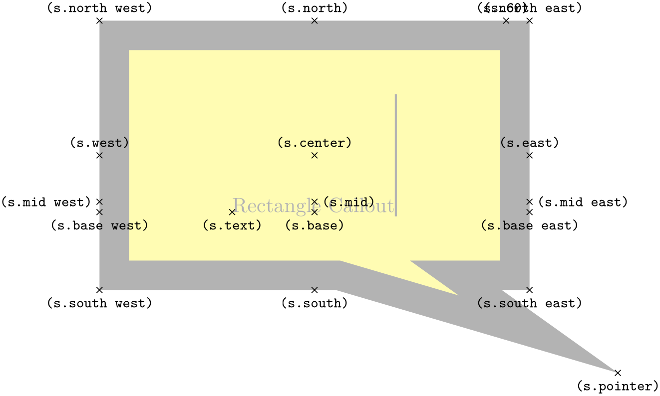
                    \usetikzlibrary {shapes.callouts}

                    \begin{tikzpicture}

                        \tikzset{callout/.style={ellipse callout, callout pointer arc=30,

                          callout absolute pointer={#1}}}

                      \draw (0,0) grid
                    (3,2);

                      \node[callout={(3,1.5)}, fill=red!50] at
                    (0,1.5) {A};

                      \node[callout={(3,.5)},  fill=green!50, callout pointer shorten=1cm]

                        at
                    (0,.5)  {B};

                    \end{tikzpicture}
-
Shape rectangle callout 
-
/pgf/callout pointer width=⟨length⟩ (no default, initially .25cm) 
This shape is a callout whose main shape is a rectangle, which tightly fits the node contents (including any inner sep). It supports the keys described above and also the following key:
Sets the width of the pointer at the border of the rectangle.
The anchors for this shape are shown below (anchor 60 is an example of a border anchor). The pointer direction is ignored when placing anchors. Additionally, when using an absolute pointer, the pointer anchor should not to be used to used to position the shape as it is calculated whilst the shape is being drawn.
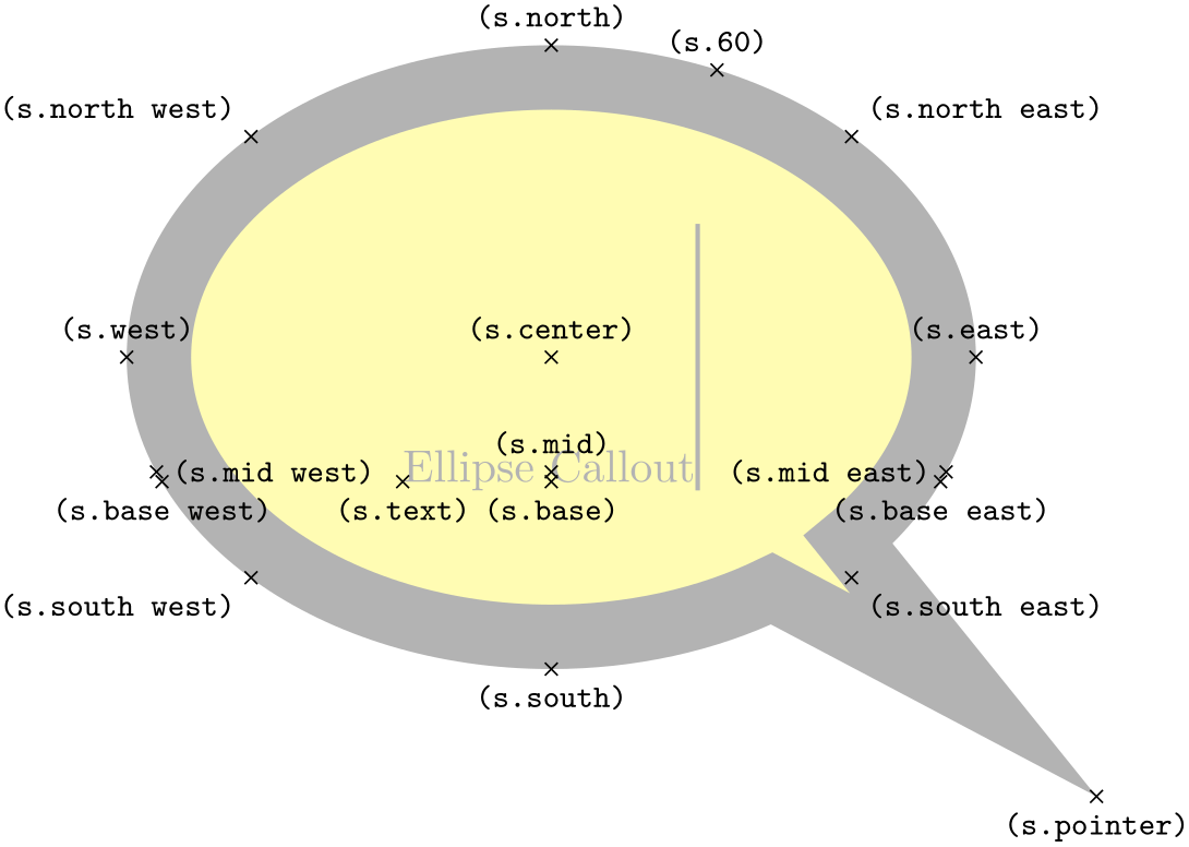
                    \usetikzlibrary {shapes.callouts}

                    \Huge

                    \begin{tikzpicture}

                      \node[name=s,shape=rectangle callout, callout relative pointer={(1.25cm,-1cm)},

                         callout pointer width=2cm, shape example, inner xsep=2cm, inner ysep=1cm]

                          {Rectangle
                    Callout\vrule width
                    1pt
                    height
                    2cm};

                      \foreach \anchor/\placement in

                        {center/above, text/below,      60/above,

                         mid/right,    mid
                    west/left,  mid
                    east/right,

                         base/below,   base
                    west/below, base
                    east/below,

                         north/above,  south/below, east/above, west/above,

                         north
                    west/above, north
                    east/above,

                         south
                    west/below, south
                    east/below,

                         pointer/below}

                         \draw[shift=(s.\anchor)] plot[mark=x] coordinates{(0,0)}

                           node[\placement] {\scriptsize\texttt{(s.\anchor)}};

                    \end{tikzpicture}
-
Shape ellipse callout 
-
/pgf/callout pointer arc=⟨angle⟩ (no default, initially 15) 
This shape is a callout whose main shape is an ellipse, which tightly fits the node contents (including any inner sep). It uses the absolute callout pointer, relative callout pointer and callout pointer shorten keys, and also the following key:
Sets the width of the pointer at the border of the ellipse according to an arc of length ⟨angle⟩.
The anchors for this shape are shown below (anchor 60 is an example of a border anchor). The pointer direction is ignored when placing anchors and the pointer anchor can only be used to position the shape when the relative anchor is specified.

                    \usetikzlibrary {shapes.callouts}

                    \Huge

                    \begin{tikzpicture}

                      \node[name=s,shape=ellipse callout, callout relative pointer={(1.25cm,-1cm)},

                        callout pointer width=2cm, shape example, inner xsep=1cm, inner ysep=.5cm]

                          {Ellipse
                    Callout\vrule width
                    1pt
                    height
                    2cm};

                      \foreach \anchor/\placement in

                        {center/above, text/below,      60/above,

                         mid/above,    mid
                    west/right,  mid
                    east/left,

                         base/below,   base
                    west/below, base
                    east/below,

                         north/above,  south/below, east/above, west/above,

                         north
                    west/above
                    left,    north
                    east/above
                    right,

                         south
                    west/below
                    left,    south
                    east/below
                    right,

                         pointer/below}

                         \draw[shift=(s.\anchor)] plot[mark=x] coordinates{(0,0)}

                           node[\placement] {\scriptsize\texttt{(s.\anchor)}};

                    \end{tikzpicture}
-
Shape cloud callout 
-
/pgf/callout pointer start size=⟨value⟩ (no default, initially .2 of callout) 
-
• A single dimension (e.g., 5pt), in which case the first ellipse will have equal diameters of 5pt.
-
• Two dimensions (e.g., 10pt and 2.5pt), which sets the \(x\) and \(y\) diameters of the first ellipse.
-
• A decimal fraction (e.g., .2 of callout), in which case the \(x\) and \(y\) diameters of the first ellipse will be set as fractions of the width and height of the main shape. The keyword of callout cannot be omitted.
-
/pgf/callout pointer end size=⟨value⟩ (no default, initially .1 of callout) 
-
/pgf/callout pointer segments=⟨number⟩ (no default, initially 2) 
This shape is a callout whose main shape is a cloud which fits the node contents. The pointer is segmented, consisting of a series of shrinking ellipses. This callout requires the shapes.callouts library (for the cloud shape). If this library is not loaded an error will result.
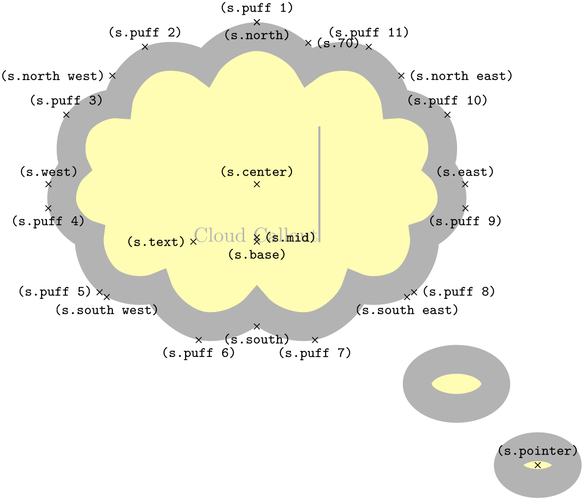
                    \usetikzlibrary {shapes.callouts}

                    \begin{tikzpicture}

                      \node[cloud callout, cloud puffs=15, aspect=2.5, cloud puff arc=120,

                        shading=ball,text=white] {\bf Imagine...};

                    \end{tikzpicture}
The cloud callout supports the absolute callout pointer, relative callout pointer and callout pointer shorten keys, as described above. The main shape can be modified using the same keys as the cloud shape. The following keys are also supported:
Sets the size of the first segment in the pointer (i.e., the segment nearest the main cloud shape). There are three possible forms for ⟨value⟩:
Sets the size of the last ellipse in the pointer.
Sets the number of segments in the pointer. Note that pgf will happily overlap segments if too many are specified.
The anchors for this shape are shown below (anchor 70 is an example of a border anchor). The pointer direction is ignored when placing anchors and the pointer anchor can only be used to position the shape when the relative anchor is specified. Note that the center of the last segment is drawn at the pointer anchor.
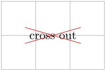
                    \usetikzlibrary {shapes.callouts}

                    \Huge

                    \begin{tikzpicture}

                      \node[name=s, shape=cloud callout, style=shape example, cloud puffs=11, aspect=1.5,

                        cloud puff arc=120,inner xsep=.5cm, callout pointer start size=.25 of callout,

                        callout pointer end size=.15 of callout, callout relative pointer={(315:4cm)},

                        callout pointer segments=2] {Cloud
                    Callout\vrule width
                    1pt
                    height
                    2cm};

                      \foreach \anchor/\placement in

                        {puff
                    1/above, puff
                    2/above, puff
                    3/above, puff
                    4/below,

                         puff
                    5/left, puff
                    6/below, puff
                    7/below, puff
                    8/right,

                         puff
                    9/below, puff
                    10/above, puff
                    11/above, 70/right,

                         center/above, base/below, mid/right, text/left,

                         north/below, south/below, east/above, west/above,

                         north
                    west/left, north
                    east/right,

                         south
                    west/below, south
                    east/below,pointer/above}

                      \draw[shift=(s.\anchor)] plot[mark=x] coordinates{(0,0)}

                        node[\placement] {\scriptsize\texttt{(s.\anchor)}};

                    \end{tikzpicture}
71.8 Miscellaneous Shapes
-
TikZ Library shapes.misc 
\usepgflibrary{shapes.misc} %
LaTeX
and plain
TeX
and pure pgf
\usepgflibrary[shapes.misc] % ConTeXt and pure pgf
\usetikzlibrary{shapes.misc} %
LaTeX
and plain
TeX
when using TikZ
\usetikzlibrary[shapes.misc] % ConTeXt when using TikZ
This library defines general-purpose shapes that do not fit into the previous categories.
-
Shape cross out 
This shape “crosses out” the node. Its foreground path are simply two diagonal lines between the corners of the node’s bounding box. Here is an example:

                    \usetikzlibrary {shapes.misc}

                    \begin{tikzpicture}

                      \draw [help lines] (0,0) grid
                    (3,2);

                      \node [cross out,draw=red] at
                    (1.5,1) {cross
                    out};

                    \end{tikzpicture}
A useful application is inside text as in the following example:
Cross
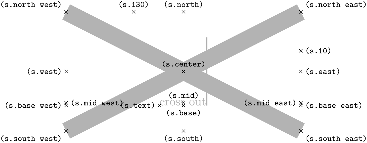 out!
out!
This shape inherits all anchors from the rectangle shape, see also the following figure:

                    \usetikzlibrary {shapes.misc}

                    \Huge

                    \begin{tikzpicture}

                      \node[name=s,shape=cross out,shape example] {cross
                    out\vrule width
                    1pt
                    height
                    2cm};

                      \foreach \anchor/\placement in

                        {north
                    west/above
                    left, north/above, north
                    east/above
                    right,

                         west/left, center/above, east/right,

                         mid
                    west/right, mid/above, mid
                    east/left,

                         base
                    west/left, base/below, base
                    east/right,

                         south
                    west/below
                    left, south/below, south
                    east/below
                    right,

                         text/left, 10/right, 130/above}

                         \draw[shift=(s.\anchor)] plot[mark=x] coordinates{(0,0)}

                           node[\placement] {\scriptsize\texttt{(s.\anchor)}};

                    \end{tikzpicture}
-
Shape strike out 
This shape is identical to the cross out shape, only its foreground path consists of a single line from the lower left to the upper right.
Strike
 out!
out!
See the cross out shape for the anchors.
-
Shape rounded rectangle 
-
/pgf/rounded rectangle arc length=⟨angle⟩ (no default, initially 180) 
-
/pgf/rounded rectangle west arc=⟨arc type⟩ (no default, initially convex) 
-
/pgf/rounded rectangle left arc=⟨arc type⟩(style, no default) 
-
/pgf/rounded rectangle east arc=⟨arc type⟩ (no default, initially convex) 
-
/pgf/rounded rectangle right arc=⟨arc type⟩(style, no default) 
This shape is a rectangle which can have optionally rounded sides.

                    \usetikzlibrary {shapes.misc}

                    \begin{tikzpicture}

                      \node[rounded rectangle, draw, fill=red!20]{Hallo};

                    \end{tikzpicture}
There are keys to specify how the sides are rounded (to use these keys in TikZ, simply remove the /pgf/ path).
Sets the length of the arcs for the rounded ends. Recommended values for ⟨angle⟩ are between 90 and 180.

                        \usetikzlibrary {shapes.misc}

                        \begin{tikzpicture}

                          \matrix[row sep=5pt, every node/.style={draw, rounded rectangle}]{

                            \node[rounded rectangle arc length=180] {180}; \\

                            \node[rounded rectangle arc length=120] {120}; \\

                            \node[rounded rectangle arc length=90]  {90};  \\};

                        \end{tikzpicture}
Sets the style of the rounding for the left side. The permitted values for ⟨arc type⟩ are concave, convex, or none.
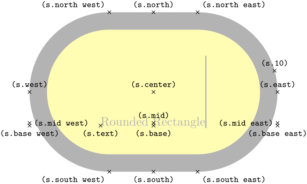
                        \usetikzlibrary {shapes.misc}

                        \begin{tikzpicture}

                          \matrix[row sep=5pt, every node/.style={draw, rounded rectangle}]{

                            \node[rounded rectangle west arc=concave] {Concave}; \\

                            \node[rounded rectangle west arc=convex]  {Convex};  \\

                            \node[rounded rectangle left arc=none]    {None};    \\};

                        \end{tikzpicture}
Alternative key for specifying the west arc.
Sets the style of the rounding for the east side.
Alternative key for specifying the east arc.
The anchors for this shape are shown below (anchor 10 is an example of a border angle). Note that if only one side is rounded, the center anchor will not be the precise center of the shape.

                    \usetikzlibrary {shapes.misc}

                    \Huge

                    \begin{tikzpicture}

                      \node[name=s,shape=rounded rectangle, shape example, inner xsep=1.5cm, inner ysep=1cm]

                          {Rounded
                    Rectangle\vrule width
                    1pt
                    height
                    2cm};

                      \foreach \anchor/\placement in

                        {center/above, text/below,      10/above,

                         mid/above,    mid
                    west/right,  mid
                    east/left,

                         base/below,   base
                    west/below, base
                    east/below,

                         north/above,  south/below, east/above, west/above,

                         north
                    west/above
                    left,    north
                    east/above
                    right,

                         south
                    west/below
                    left,    south
                    east/below
                    right}

                         \draw[shift=(s.\anchor)] plot[mark=x] coordinates{(0,0)}

                           node[\placement] {\scriptsize\texttt{(s.\anchor)}};

                    \end{tikzpicture}
-
Shape chamfered rectangle 
-
/pgf/chamfered rectangle angle=⟨angle⟩ (no default, initially 45) 
-
/pgf/chamfered rectangle xsep=⟨length⟩ (no default, initially .666ex) 
-
/pgf/chamfered rectangle ysep=⟨length⟩ (no default, initially .666ex) 
-
/pgf/chamfered rectangle sep=⟨length⟩ (no default, initially .666ex) 
-
/pgf/chamfered rectangle corners=⟨list⟩ (no default, initially chamfer all) 
This shape is a rectangle with optionally chamfered corners.

                    \usetikzlibrary {shapes.misc}

                    \begin{tikzpicture}

                      \node[chamfered rectangle, white, fill=red, double=red, draw, very thick]

                        {\bf STOP!};

                    \end{tikzpicture}
There are pgf keys to specify how this shape is drawn (to use these keys in TikZ simply remove the /pgf/ path).
Sets the angle from the vertical for the chamfer.

                        \usetikzlibrary {shapes.misc}

                        \begin{tikzpicture}

                          \tikzset{every node/.style={chamfered rectangle, draw}}

                          \node[chamfered rectangle angle=30] {abc};

                          \node[chamfered rectangle angle=60] at
                        (1.5,0) {123};

                        \end{tikzpicture}
Sets the distance that the chamfer extends horizontally beyond the node contents (which includes the inner sep). If ⟨length⟩ is large, such that the top and bottom chamfered edges would cross, then ⟨length⟩ is ignored and the chamfered edges are drawn so that they meet in the middle.
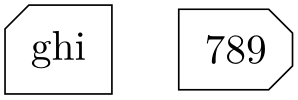
                        \usetikzlibrary {shapes.misc}

                        \begin{tikzpicture}

                          \tikzset{every node/.style={chamfered rectangle, draw}}

                          \node[chamfered rectangle xsep=2pt] {def};

                          \node[chamfered rectangle xsep=2cm] at
                        (1.5,0) {456};

                        \end{tikzpicture}
Sets the distance that the chamfer extends vertically beyond the node contents. If ⟨length⟩ is large, such that the left and right chamfered edges would cross, then ⟨length⟩ is ignored and the chamfered edges are drawn so that they meet in the middle.
Sets both the xsep and ysep simultaneously.
Specifies which corners are chamfered. The corners are identified by their “compass point” directions (i.e. north east, north west, south west, and south east), and must be separated by commas (so if there is more than one corner in the list, it must be surrounded by braces). Any corners not mentioned in ⟨list⟩ are automatically not chamfered. Two additional values chamfer all and chamfer none, are also permitted.

                        \usetikzlibrary {shapes.misc}

                        \begin{tikzpicture}

                          \tikzset{every node/.style={chamfered rectangle, draw}}

                          \node[chamfered rectangle corners=north west] {ghi};

                          \node[chamfered rectangle corners={north east, south east}] at
                        (1.5,0) {789};

                        \end{tikzpicture}
The anchors for this shape are shown below (anchor 60 is an example of a border angle.
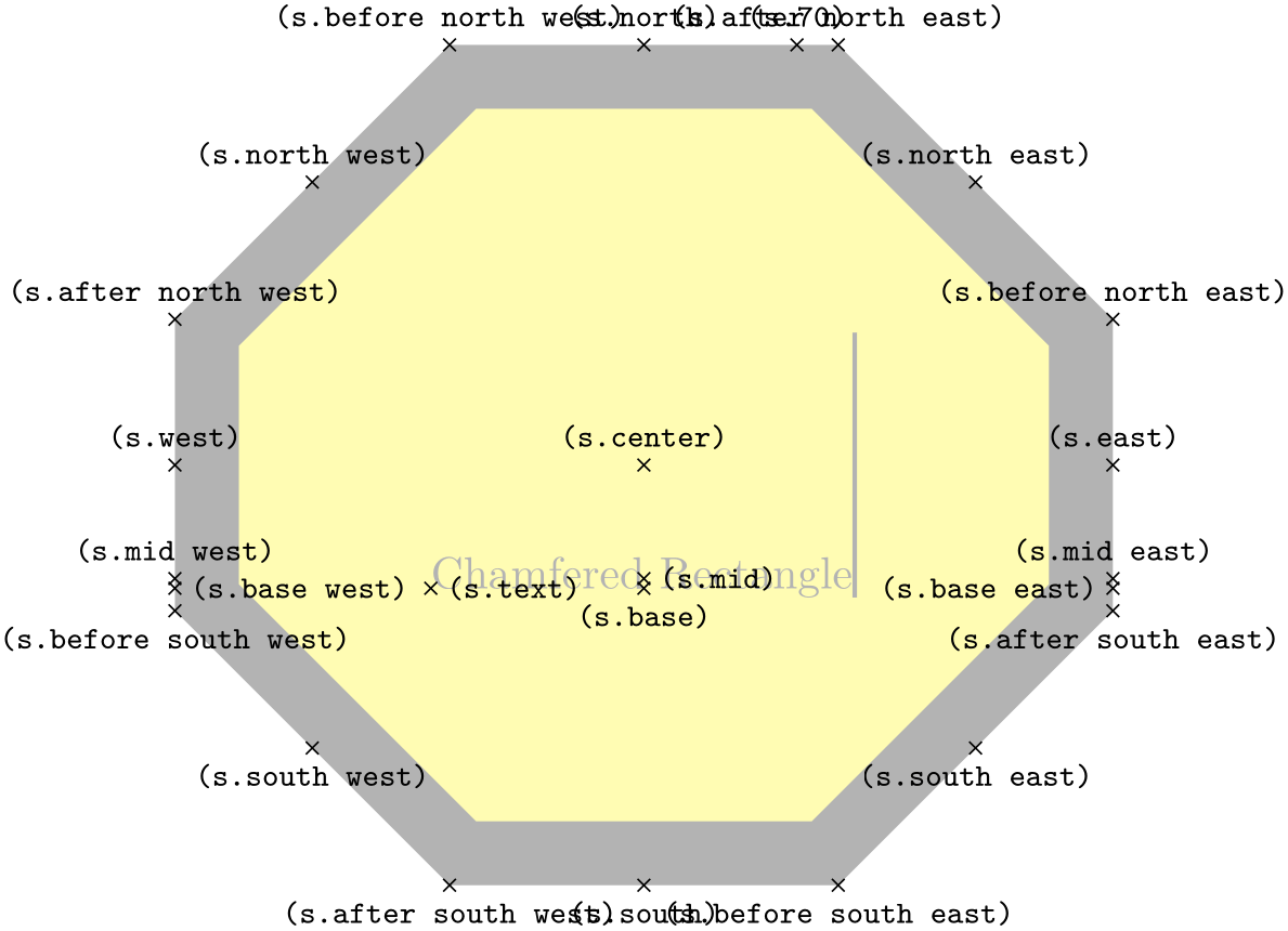
                    \usetikzlibrary {shapes.misc}

                    \Huge

                    \begin{tikzpicture}

                      \node[name=s,shape=chamfered rectangle, chamfered rectangle sep=1cm,

                            shape example, inner ysep=1cm, inner xsep=.75cm]

                        {Chamfered
                    Rectangle\vrule width1pt
                    height2cm};

                      \foreach \anchor/\placement in

                        {text/right, center/above,    70/above,

                         base/below, base
                    east/left, base
                    west/right,

                         mid/right,  mid
                    east/above,   mid
                    west/above,

                         north/above, south/below, east/above, west/above,

                         before
                    north
                    east/above, north
                    east/above, after
                    north
                    east/above,

                         before
                    north
                    west/above, north
                    west/above, after
                    north
                    west/above,

                         before
                    south
                    west/below, south
                    west/below, after
                    south
                    west/below,

                         before
                    south
                    east/below, south
                    east/below, after
                    south
                    east/below}

                         \draw[shift=(s.\anchor)] plot[mark=x] coordinates{(0,0)}

                           node[\placement] {\scriptsize\texttt{(s.\anchor)}};

                    \end{tikzpicture}