chemfig
Reaction schemes
10 Arrows customization
This section is quite technical and requires some knowledge of TikZ. It is targeted at advanced users only who need to define their own arrows.
The \definearrow command allows to build custom arrows. Its syntax is:
\definearrow{⟨number⟩}{⟨arrow name⟩}{⟨code⟩}
where ⟨number⟩ is the number of optional arguments that will be used in the ⟨code⟩, with the usual syntax #1, #2, etc. These optional arguments cannot accept default values; if no value is specified upon using the macro \arrow, the arguments will remain empty.
Before going further, let’s examine the available internal macros when drawing arrows. Since these macros include the "@" character in their name, they can only be accessed between \catcode`\_=11 and \catcode`\_=8 commands.
\CF_arrowstartname and \CF_arrowendname include the names of the compounds (considered as nodes by TikZ) between which the arrow is drawn;
\CF_arrowstartnode and \CF_arrowendnode include the node names where arrow ends will be located. After these names, user-defined anchors can be specified in the argument between brackets of the \arrow command, unless the field is left empty;
\CF_arrowcurrentstyle and \CF_arrowcurrentangle contain the style and the angle of the arrow to be drawn;
\CF_arrowshiftnodes{⟨dim⟩} shifts the nodes “\CF_arrowstartnode” and “\CF_arrowendnode” perpendicularly relative to the arrow by a dimension specified in the argument;
\CF_arrowdisplaylabel{#1}{#2}{#3}{#4}{#5}{#6}{#7}{#8} is the most complex one. It gives the labels position with the following arguments:
#1 and #5 are the labels to be written;
#2 and #6 are real numbers between 0 and 1. They specify the location of the labels on the arrow. 0 is the beginning of the arrow and 1 is its end, assuming a straight arrow;
#3 and #7 are the “+” or “-” characters. “+” displays the label above the arrow, while “-” does it below it;
#4 and #8 are the names of the nodes corresponding to the beginning and the end of the arrow.
arrow heads are based on “CF” for a full arrow and have the “harpoon” option for half arrows.
10.1 First arrow
As an example, assume we want to make an arrow with a circle on its center. Let’s call it “-.>”. This arrow will accept four optional arguments. Like for previously-defined arrows, the first and second arguments will be the labels to be located above and below the arrow. The third one will define the perpendicular shift relative to the arrow direction. Finally, the 4th argument will define the circle size. If this last argument is absent the default circle size will be equal to 2pt.
Let’s start with \definearrow{4}{-.>} to declare that the arrow will have 4 optional arguments and that it will be called -.>. First, the position of the nodes between which the arrow is to be drawn must be modified in order to take the third-argument shift into account. This is made with the macro \CF_arrowshiftnodes, so the code of the arrow will start with: \CF_arrowshiftnodes{#3}%. Then, one must plot the arrow itself, while taking the opportunity to set a node on the center of the segment, which will be called "mid@point". Finally, the circle is defined with its center on that node. The whole TikZ code is:
\edef\pt_radius{\ifx\empty#4\empty 2pt\else #4\fi}% circle radius0pt \expandafter\draw\expandafter[\CF_arrowcurrentstyle,-CF] (\CF_arrowstartnode)--(\CF_arrowendnode)coordinate[midway](mid@point); \filldraw(mid@point)circle(\pt_radius);%
The last step is to enter the labels, if any, with the folwing line:
\CF_arrowdisplaylabel{#1}{0.5}{+}{\CF_arrowstartnode}{#2}{0.5}{-}{\CF_arrowendnode}
Here is the completed arrow:

\catcode`\_11

\definearrow4{-.>}{%

  \edef\pt_radius{\ifx\empty#4\empty 2pt\else #4\fi}% dot radius

  \CF_arrowshiftnodes{#3}%

  \expandafter\draw\expandafter[\CF_arrowcurrentstyle,-CF](\CF_arrowstartnode)--(\CF_arrowendnode)

    coordinate[midway](mid@point);

  \filldraw(mid@point)circle(\pt_radius);%

  \CF_arrowdisplaylabel{#1}{0.5}{+}{\CF_arrowstartnode}{#2}{0.5}{-}{\CF_arrowendnode}

  }

\catcode`\_8

\schemestart

A \arrow{-.>} B \arrow{-.>[above][below][][1pt]} C \arrow{-.>[][below]}[30] D \arrow{-.>[above][][5pt][1.5pt]} E

\schemestop
10.2 Curved arrow
How about a curved arrow? To make things as simple as possible, assume it will have one single optional argument with the TikZ code that will specify the point(s) of control. If this argument is empty, a “-CF” type arrow will be plotted.
If #1 is not empty, attention should not be drawn to “\CF_arrowstartnode” and “\CF_arrowendnode” which contain the node names of arrow ends positions, because the location of these nodes is already determined by the anchors calculated for straight arrows! Instead we will use \CF_arrowstartname and \CF_arrowendname which contain the names of the compound (which are nodes for TikZ), since the arrow must be plotted between them. Here’s the TikZ code to draw the curved arrow between the two compounds:
\draw[shorten <=\CF_arrowoffset,shorten >=\CF_arrowoffset,\CF_arrowcurrentstyle,-CF,0pt (\CF_arrowstartname).. controls #1 ..(\CF_arrowendname);%
One must add a TikZ code to shorten the arrow by an amount \CF_arrowoffset defined by \setarrowoffset. Indeed, the nodes ar not the same as those for straight arrows (\CF_arrowstartnode and \CF_arrowendnode). So before \CF_arrowcurrentstyle, the following code must be added:
shorten <=\CF_arrowoffset, shorten >=\CF_arrowoffset
this is the role the two lines after \else.
So here is our curved arrow:
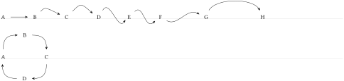
\catcode`\_11

\definearrow1{s>}{%

\ifx\empty#1\empty

  \expandafter\draw\expandafter[\CF_arrowcurrentstyle,-CF](\CF_arrowstartnode)--(\CF_arrowendnode);%

\else

  \def\curvedarrow_style{shorten <=\CF_arrowoffset,shorten >=\CF_arrowoffset,}%

  \CF_eaddtomacro\curvedarrow_style\CF_arrowcurrentstyle

  \expandafter\draw\expandafter[\curvedarrow_style,-CF](\CF_arrowstartname)..controls#1..(\CF_arrowendname);

\fi

}

\catcode`\_8

\schemestart

A\arrow{s>}

B\arrow{s>[+(0.5cm,0.5cm)]}

C\arrow{s>[+(45:1cm)]}

D\arrow(.60--.120){s>[+(60:1cm) and +(-120:1cm)]}

E\arrow{s>[+(45:1) and +(-135:1)]}

F\arrow{s>[+(-30:1) and +(150:1)]}[,1.5]

G\arrow(.90--.90){s>[+(60:1)and+(120:1)]}[,2]

H

\schemestop


\schemestart

A\arrow(.90--.180){s>[+(90:0.8) and +(180:0.8)]}[45]B

\arrow(.0--.90){s>[+(0:0.8) and +(90:0.8)]}[-45]C

\arrow(.-90--.0){s>[+(-90:0.8) and +(0:0.8)]}[-135]D

\arrow(.180--.-90){s>[+(180:0.8) and +(-90:0.8)]}[135]

\schemestop